Picking the Right Sensor for Your Design
To select the optimal sensor, you must be aware of the interdependencies and interactions of many attributes and factors. In the end, it's still a series of tradeoffs.


Latest News
April 1, 2010
By Tom Kevan
Methodologies such as mechatronics and systems engineering stress the importance of the interdependencies of all domains in design. To create a successful product, you must operate on the principle that the performance characteristics of one component can have a major effect on those of another. The selection of sensors for designs only reinforces this principle.
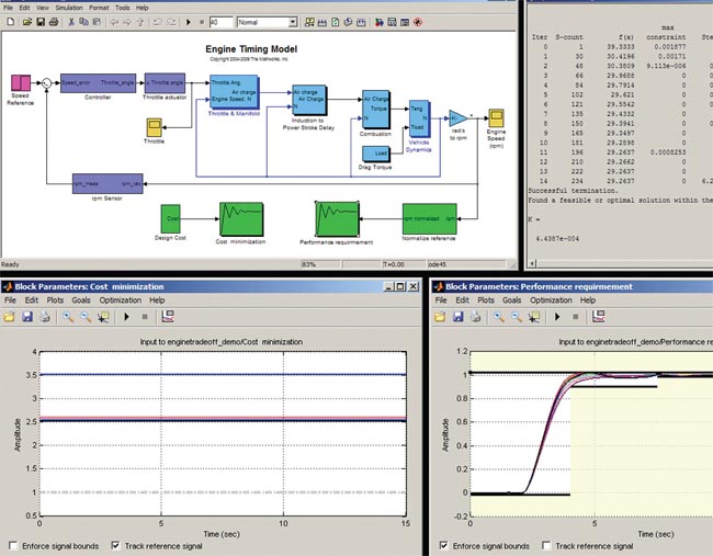 Figure 1: Designers optimize an engine-timing model in Simulink to automatically find the combination of controller gains and sensor accuracy (above, right) that minimizes cost (below, left) and maintains specified controller performance (below, right). Image courtesy of The MathWorks |
Choosing the right sensor for an application is a balancing act of juggling factors such as architecture, range, accuracy, repeatability, resolution, output, noise, bandwidth, power, communications, and expense. By understanding the interactions among the relevant attributes, you can make intelligent tradeoffs and select the right sensor for the application.
Sensor Offerings Advanced Motion Sensing / Consumer Features Wireless Range Extender Features Multipurpose Digital Pressure Sensor Features |
The Larger Picture
The first step in selecting a sensor is the definition of the system and architecture in which the sensor will function. From this larger “picture,” you determine what physical properties must be measured and, thus, what types of sensors are required.
Once you’ve narrowed the field of sensors from which you can make your selection, you determine whether you are making a direct or indirect measurement. A temperature sensor provides a direct measurement. On the other hand, if you are measuring force or velocity, you may have to make an indirect measurement. “If you want to measure a force, you can use an accelerometer and then compute force from that,” says Alex Gomez, a principal engineer at Boston Engineering, a leading engineering service provider. “If you are trying to measure velocity, the easiest way is to use an encoder. That gives you position, and from position, you derive velocity.”
Attributes
Your next step in the selection process is to identify the important sensor attributes, which vary with each application, and then match each sensor candidate’s performance with the application’s requirements. At this stage, you’re looking at range, accuracy, repeatability, and resolution.
An example of a range consideration can be seen in the selection of an accelerometer. In this case, you may be interested in sub-G accelerations or accelerations involving hundreds or thousands of Gs. Then later would be an application requiring shock and vibration measurements. Reliable vendors provide good benchmarks that help you evaluate each sensor’s attributes.
Now evaluate electrical issues within the context of the product’s architecture and the processor receiving the sensor’s signals. One of the leading concerns here is the device’s output. Sensor outputs come in a number of forms. The most common are voltage (e.g., 0-5 V), current (e.g., 4–20 mA), and serial (e.g., RS-232, I2C, and parallel).
To choose the right output, you have to look at the application and determine some basic performance requirements, starting with the speed of the acquisition required. “If you need to acquire very fast signals because your process requires it, you may want to go to an analog output and use a fast A/D converter,” says Gomez. These features give you more control over how often you are sampling.”
If you are concerned about noise, an analog sensor may not be the best option. Noise tends to be a bigger problem with analog sensors. A better choice might be to use a digital device that generates a serial output. These sensors are often slower Than analog sensors, so there is a tradeoff for signal integrity over speed.
Physical properties tend to change at different paces. For example, if you are measuring temperature, you don’t require a high sampling rate because temperature changes relatively slowly. In that case, you can use a digital temperature sensor, but they tend to be more expensive.
In other situations, however, you need high sampling rates. For example, if you are going to use a sensor to control a motor that operates at 35,000 RPM, you want a sensing device that takes many measurements quickly. In that case, you would use either an analog velocity sensor or a very fast pulse-type of output. With analog, you can acquire data very fast.
Tools of the Trade
There are a number of tools that facilitate sensor selection. Some are available on vendor Web sites gratis. For example, Analog Devices offers tools, software, and simulation models tailored for specific components to assist with design goals and criteria. Others are homegrown by individual service providers, such as Boston Engineering’s power consumption spreadsheet, which its engineers use to determine power dissipation in an application.
Then there are tried and true commercial software applications that validate sensor selections before designs are completed and resources are expended. “We use MathWorks’ Simulink to simulate sensors and controls, with the effects of noise factored in to get a better understanding of feasibility,” says Gomez. “The better you make your simulation, the less the risk. The key is you have some high fidelity that you are inserting into your model and simulation. You are inserting the proper attributes of the sensor, so you see if it will succeed or fail (see Figure 1).
More Info:
Analog Devices
Contributing Editor Tom Kevan is based in New Hampshire and is DE’s mechatronics, PLM, and systems expert. Send your comments about this article to [email protected].
Subscribe to our FREE magazine, FREE email newsletters or both!
Latest News
About the Author
DE’s editors contribute news and new product announcements to Digital Engineering.
Press releases may be sent to them via [email protected].


