PolyWorks 10
Inspection or reverse-engineering tool, this solution has the flexibility to fit into your process wherever you want.


Latest News
December 10, 2007
By Al Dean
 For many, the goal of the reverse engineering process will be the creation of a NURBS-based surfacemodel that can be used in more traditional CAD systems. |
PolyWorks, developed by InnovMetric of Quebec, is split into two products, and your choice of package will depend entirely on the workflow it must fit. One version is a reverse-engineering tool intended to produce highly accurate polygonal models and NURBS surfaces exportable to any downstream application, while the other is a means of inspecting physical objects and comparing them to the ideal MCAD data from which they were manufactured. Both are built on the same core application, so we’ll take a look at that before exploring the task-specific tools.
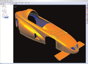
PolyWorks 10 begins with a new UI where everything is standard in appearance and enables enhanced customization. All operations are driven by customizable toolbars around the screen to keep the workspace as uncluttered as possible. This ensures that users have access to the commands they commonly use, which can be standardized easily and distributed using Visual Layout files. And the system has been updated to be 64-bit compatible, so those looking to work with truly huge datasets can take advantage of more powerful workstations.
 Noncontact scanning devices often produce a few errors — it would be a rare job indeed where the form of a part was captured 100 percent. So as aresult, hole finding and filling is essential for the software to accomplish. | 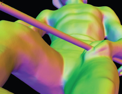 PolyWorks includes both automated tools that can deal with the majority of problems sensibly, and also provides the manual tools you need to dealwith the really tricky problems. |
Data import
The starting point is to read in the data from your capture device. PolyWorks can read almost any format you can imagine. It includes all of the usual suspects in terms of STL, ACSII text, but where it really excels is in reading native formats from a wide range of scanners using a range of plug-ins (including Faro, Leica, Minolta, Perceptron, and Steinbichler).
This is good news because for each pass of a laser or an area-based photogrammetry scanner across the surface of a part, a single file or package is created and these need to be aligned or registered. Outputting these to a standard, lowest-common-denominator format such as ASCII file means that PolyWorks will only have access to information about the location of each point and its position in space (typically as an x,y,z coordinate). By reading native data formats, more information is retained (such as the position and orientation of the scanning head) and this can be used to register each scan set more efficiently and effectively. When loading data, the system runs through an auto-organization process that extracts the data for each stripe and optimizes it by removing errors using that fuller description. Of course, there are also going to be areas of overlap and mismatch, so PolyWorks includes a range of tools to initially find the deviation between stripe s, fix areas by shuffling the stripes to achieve a closer match, and then find and remove overlaps. The end result is a higher quality point cloud and by increasing the quality of the mesh, you have higher quality data on which to base downstream proc-esses. From here the workflows bifurcate into reverse engineering and inspection, so let’s split them apart.
PolyWorks/Modeler
If you’re looking to build high-quality polymeshes or ultimately surface models, you need to work with the point-cloud data. There are always areas that can’t be accessed effectively as errors are introduced or data is missing; that’s the nature of the beast. What’s critical is that any application can handle these problems in a meaningful way.
It’s not prudent to go through every postprocessing tool within PolyWorks’ arsenal; facts are that it has everything to fix mesh problems — but let’s have a look at a few that impressed us. One of the most common problems is holes. While PolyWorks has a range of manual hole-filling tools, the automated ones will get you there more quickly. A single command can create either a planar fill or a curvature-maintaining patch. A layer of triangles is stripped back around those holes to clean it up, then the surface is patched — the result is a much more pleasing fill process.
Another interesting operation is the Fill-in Surface command. You sketch a polygon around the hole, a surface is created within that polygon, matched to the surrounding geometry, patched in, and then finally tessellated to create a continuous polygon mesh. The intelligence in these commands, with the setback of triangles before moving forward with the operation, is found in many other commands. For example, the Edge Clean Up tools are particularly intelligent. Noncontact devices don’t handle sharp edges well, so PolyWorks includes tools to remove the edges and rebuild them based on surrounding geometry. The result is good-quality, sharp edges that reflect your intent. Taken further, this type of technique can also be used to rebuild filleted edges or rounded forms, which, again match design intent.
PolyWorks has a very rich set of polygon mesh modeling and editing tools, the goal of which is a quality mesh that provides what you need. This might sound a little vague, and for good reason. This technology is used across a wide industrial spectrum and the workflow will differ from one to another. If you’re looking to perfectly replicate a physical object, then your work will focus on rebuilding areas that can’t be scanned or on errors that have been introduced, with the aim of retaining the same properties of your physical object.
It’s eminently possible to take a polygon mesh into production these days, after all, CAM systems tessellate a surface model anyway — so why do the same thing twice? If you’re seeking to capture a physical object and use it as the basis for further design work, then perhaps you’re going to need to take the polygon mesh further and create a surface model.
PolyWorks has a full set of surfacing operations tailored to working from a mesh. This can be done using the offsetting commands that allow you to take a polygon mesh, create an offset skin (still using triangles) to create a thickened surface skin with automatically created walls, and includes a water-tightness check. Or you might be looking to create a surface patchwork across your polygon mesh.
The system supports your way of working, whether you go for a quick, automatically created patchwork of surfaces to read into your MCAD system, or dive in to create guide curves to give the system something more structured onto which you can then build individual surfaces. There are tools to assist with creating mirrored forms and the surface-creation process will retain any curvature you need, including G1 and G2 continuity across the mirror plane.
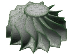 Here a turbo machinery component has been scanned and the mesh improved, edges have been rebuilt (these are typically difficult to scanaccurately), fillets added where needed, sharpened elsewhere. | 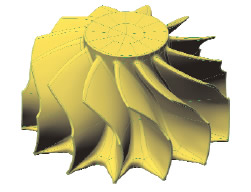 The resultant NURBS surface model is high quality, and can be inspected against the original scan data or the improved polygon mesh wheneverneeded to ensure that it maintains the form required. |
PolyWorks/Inspector
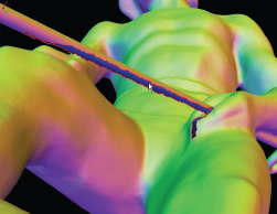
The PolyWorks/Inspector variant differs by requiring that you load the scanned data of your physical part or the nominal MCAD model from which it’s manufactured. An initial best-fit alignment is performed to create a rough alignment. You then use a number of techniques to align it further: as a 321 alignment (where three common points are used to align the two sets), or using geometry references, such as circular features or planes.
Once the system has the two datasets aligned, you can see a comparison of points to MCAD data, which is color- mapped to show deviation and adapted to your tolerance requirements. Once you have the view in the state that you want, you then create a SnapShot. This captures the view, inspection details, how it’s displayed, etc. Each of these is then used in the Inspection report. Cross sections can be used to extract deviation and are particularly suited to applications where these technologies are used to replicate accepted and validated manual techniques, such as gauges, calipers, as well as pretty auto-motive-specific gap-and-flush concerns. The system will also create more textural information in tables to fully show the tolerances and deviations between the nominal and the manufactured component. This can be customized to show exactly the information you require.
Essentially, PolyWorks includes all of the tools you need to replicate your existing and fully certified inspection processes, but using a technology that allows you to capture a much larger, more descriptive understanding of your part’s quality than using traditional manual or CMM-based processes. Also, it’s ideal for automation — you scan each part you’re inspecting, run a macro that performs all of these processes, and generate your report. Hence, your inspection process becomes more compressed. What’s interesting is that in addition to providing print-based or digital files such as PDFs, you can also share the inspection datasets and use the freely distributable PolyWorks 3D Viewer application. It enables those who need to to access that full, rich inspection data alongside the more traditional report.
Wrapping It Up
As discussed, the potential workflows for PolyWorks vary hugely, making it difficult to zero in on one potential use for PolyWorks. What I can tell you is that the system has several concepts at its core. Ease of use is a must for every piece of software on the market today, and here PolyWorks excels. The UI is clean and adaptable to your requirements, either as an individual user or for the purposes of company-wide standardization.
This latter use is particularly interesting. It’s commonly the case that organizations involved in reverse engineering have a range of capture hardware across different departments, all with different usage models. By standardizing on a single platform — yet retaining the ability to customize the department or task-specific implementations — technical support is reduced. So are acquisition and on-going costs; you’re using a single system to perform multiple tasks. Another key concept is that of providing intelligent automation tools that let you quickly perform common tasks in a shorter space of time, but this must always be tempered with the ability to dive in and use more manual tools to solve problems that always arise with any scanning job. PolyWorks has both sets of tools by the bucket load.
The conclusion should be that what-ever the reverse-engineering or inspection-related task you’re performing, PolyWorks has tools that can assist with completing it in the shortest time possible. PolyWorks lets you make the most of your capture device investment and make the most of your processes. And when it comes to software designed for the product development and manufacturing process, where time — as the cliché goes — is money, it’s a winner.
More Information
Innovmetric
Quebec, QUE
innovmetric.com
Al Dean is technology editor at MCAD Magazine, a UK product development and manufacturing technology journal (mcadonline.com) and is editor of Prototype magazine (prototypemagazine.com). You can send comments about this article to DE-Editorsmailto:[email protected].
Subscribe to our FREE magazine, FREE email newsletters or both!
Latest News
About the Author
DE’s editors contribute news and new product announcements to Digital Engineering.
Press releases may be sent to them via [email protected].


