

Latest News
October 1, 2010
By Christopher Hardee
Designing and building a car is like composing and performing a symphony. CAD designers and CAE analysts act like a team of composers, drawing upon their creativity, the laws of physics, and a host of engineering software tools to create a design “score.” Then the instrumental sections—the powertrain, electrical, exhaust, steering, and other systems—bring the composition to life. Revisions and rehearsals follow. Finally the premier arrives, and when everything is in sync, the orchestra of components produces an on-the-road performance in perfect pitch. With the right talent and tools, the results can be music to the market.
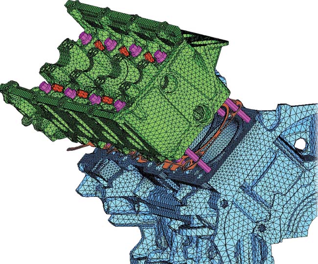 Figure 1: Model of engine block and cylinder head for a cylinder head deck lift analysis. |
In more straightforward terms, designing an automobile is an extremely complex endeavor. Ford Motor Company’s North America Engine Engineering Organization, for example, has more than 100 CAD designers and CAE analysts in the Powertrain Analytical Design and Six Sigma (ADSS) department alone. This team has responsibility for the design of all of the powertrain components, including the cylinder block and head, connecting rods and crankshafts, pistons, turbo chargers, and valvetrains. To manage this task with a Six Sigma mindset and develop the most robust designs in the shortest amount of time is a challenge that requires precise inter- and intra-departmental coordination, robust engineering tools, and well-tuned processes.
With those coordination goals in mind, Ford created a global program to improve product development efficiency, increase throughput, and deliver 100% geometric compatibility. As part of this PLM effort, they implemented a series of digital innovation initiatives, one of which—Digital Vehicle Engineering (DVE)—includes development of multiple intelligent CAD templates with tight integration of CAE and optimization modules. The goal is to promote enhanced collaboration among engineers, designers, and analysts in a virtual product design and verification environment.
First Movement: CAD and CAE Integration
About five years ago Ford made the decision to migrate all CAD model building to CATIA, the Dassault Systèmes’ brand for virtual design and product innovation.
“What made the difference for the management team was the capability of CATIA to integrate CAE tools,” says Jeffrey Bautz, Ford’s ADSS manager. “They recognized that the resulting efficiency improvements would be significant.”
The ADSS team saw potential benefits for the powertrain system and was one of the first groups to use the integrated CATIA CAD/CAE solution for production inside Ford. To implement this solution, the team chose Abaqus for CATIA (AFC), a solution from the Dassault Systèmes’ SIMULIA brand that brings the FEA capabilities of Abaqus into the CATIA environment through two CATIA workbenches—nonlinear structural analysis and thermal analysis.
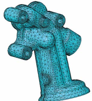 Figure 2: Model for an oil filter adaptor noise, vibration, and harshness (NVH) analysis. |
When the ADSS team began using AFC to integrate CAD and CAE within CATIA, they were able to greatly accelerate the analysis process. With the CAE model and the CAD geometry easily accessible in one interface, the workbenches enabled the team to do multiple iterations quickly. Using an integrated platform, there is “associativity” between the geometry and analysis models, no time delays between steps, and a much more streamlined workflow.
Second Movement: Template Development
In search of even greater efficiencies, the ADSS team next focused on automating the CAD and CAE processes and recognized the Abaqus for CATIA environment as being robust enough to handle this task. With this in mind, the team embarked on a path of developing software templates to facilitate process automation—starting with CAD templates about two years ago, followed by the CAE templates roughly one year later. The team realized, in developing templates to use inside CATIA, that there were tremendous opportunities to improve product development cycle times.
“With integrated CAD/CAE templates as part of our DVE strategy, we are able to accelerate the initial geometry and analysis generation process,” says Sassan Khoubyari, PLM strategy and implementation manager. “This allows CAE to drive design upfront, rather than validating later in the design process.”
Since an analysis is only as good as the analyst’s assumptions, the team spends a tremendous amount of time developing their methodology. The process consists of multiple iterations between physical test data and the model to ensure correlation. Once assumptions are validated, capturing their value is important. Templates do that, standardizing the conditions and variables for a model or simulation. They can then be used to guide each engineer on the team down a single analysis path that’s proven and repeatable.
Once a method for building a complicated model—like for a cylinder head— has been developed, the analyst must still apply a huge number of different boundary conditions, contact elements, and loads. It is possible to have cases with 250 to 300 different types of boundary conditions in a single model. Before templates, most of that work was done manually. With hundreds of components in the powertrain and multiple iterations for many analyses, it’s easy to imagine the extra time spent crosschecking designs. Simply put, templates minimize the potential for human error while saving time.
To get started, the ADSS team used a 6-Sigma-like approach and developed value stream maps for all of the major engine components—for the cylinder head, the block, the connecting rod, the exhaust and intake manifolds, to name just a few. The value stream maps were used to prioritize component template development, the goal being to identify those templates that could potentially improve the product development cycle most dramatically.
First, the team chose to test an oil filter adaptor analysis, because it was relatively simple, could be completed quickly, and could serve as a template proving ground. This analysis template included parameterized ribbing (see Figure 2). They also chose a cylinder head lift deck rigidity analysis, a much more complicated project, because it would test CATIA’s ability to handle complex CAE templates. This analysis template included a variety of features:
- Automatic set-up of 51 contact pairs and 71 constraints.
- Creation of parameterized components including steel plates, head bolts, plugs for spark plug and injector holes.
- Elastic-plastic material property of head bolts.
- Geometry partition and grouping of a combustion chamber surface to define the mesh boundary for a cylinder pressure application.
- Five analysis steps, including press-fit of valve seats, bolt down of a cylinder head with steel plates and, finally, peak combustion pressure application in each cylinder head respectively (see Figure 1).
Both analysis templates were attractive candidates because they are current production programs in the early phases of development where there is a tendency to do many iterations.
The team uses Excel spreadsheets that are attached to the templates with all the key parameters. The CAD template defines the geometry. The CAE template includes the basic information for the simulation—the mesh, load, and boundary condition requirements. Because the templates are linked, a CAE analyst can easily change the key parameters, which then automatically updates the geometry along with the mesh in the analysis model. In addition, for further consistency across the department, the CAD and CAE groups now have standardized hardware and are working on high-end PCs in a Microsoft Vista environment.
Third Movement: Benchmarking Efficiencies and Savings
Two years into the CAD/CAE integration, the ADSS team has made improvements in the product development cycle for a number of powertrain components. The team now has CAD templates for all the major components and has begun to actualize the return on investment, with long-term impacts lining up to be significant.
For an accounting of the specific improvements, Bautz turns to his team leaders. According to John Norcut, CAD template development manager, the oil filter adaptor analysis has been greatly improved. “By eliminating the CAD-to-CAE-to-CAD hand-offs, there has been a savings of three to four weeks overall in product development cycle time,” Norcut says.
“For the cylinder head deck lift analysis, it used to take an analyst one to two days to set up the model,” says Alex Tang, CAE technical specialist in charge of the CAE template development effort. “But with the template and a CAE-ready model, set-up time has been reduced to less than 30 minutes.”
Improvements are equally dramatic for other components. To mesh the connecting rod for a dynamic analysis, it used to take an experienced analyst as much as four to eight hours. With templates, it can now be done in as little as 10 minutes if the CAD model is clean. For an intake manifold burst analysis, mesh generation has been collapsed from three weeks to only about two hours. For a connecting rod durability analysis, a one-and-a-half week mesh-time has shrunk to minutes.
As a result of these gains, the ADSS team is looking at ways of bringing additional analysis tools inside CATIA as well. Their plan for the future includes the use of SIMULIA’s Isight optimization software. This tool provides a visual and flexible process of automating the exploration of design alternatives and identifying optimal performance parameters.
Fourth Movement: Quality on the Road
The CAE integration and template effort will have a number of long-term impacts, including a change in workflow. CAD designers and D&R engineers, rather than CAE analysts, will be able to handle many of the simple analyses. As a result, analysts will gain time to tackle more difficult problems—such as higher-end analyses and new methods development—that require their level of training and expertise. This workload balancing will further improve design validation efficiency because every new method will allow the team to eliminate a hardware test.
And fewer hardware tests mean substantial cost savings.
The template initiative is now being deployed throughout Ford’s operations globally. What’s more, the initiative is in synchrony with Ford President and CEO Alan Mulally’s ONE Ford plan to accelerate development of new products that customers want and value.
From powertrain solo to full automotive system symphony, the results of design improvements at Ford are already on the road today, and the consumer is the ultimate beneficiary. For the past three years, Ford vehicles have been statistically proven to be equivalent in quality to those of its leading competitors. With CAE integration now added to the design composition, the harmonies of automotive performance are only going to get that much tighter and sweeter.
More Info:
CATIA
Christopher Hardee is a freelance science and technology writer based in New Hampshire. Contact him via [email protected].
Subscribe to our FREE magazine, FREE email newsletters or both!
Latest News
About the Author
DE’s editors contribute news and new product announcements to Digital Engineering.
Press releases may be sent to them via [email protected].


