Rapid Tech Choices for 3D Part Production
How users match materials and systems for building prototype or production parts.


Latest News
June 1, 2011
By Pamela J. Waterman
Ever go into a certain ice-cream shop and find that 31 choices are almost too many? Designers and manufacturers may find the same problem when it’s time to create either a prototype or an end product using rapid manufacturing systems. It’s a good problem to have, but how do you choose among the dozens of possible fabrication techniques and raw material types?
DE asked officials and customers of four companies—Envisiontec, EOS, Roland DGA and ZCorp—what factors determined application choices. Their answers may help you decide which solution’s flavor will work best.
Organic Curves and Smooth Finishes
“A big part of what we do is trying to understand what (customers) are using the rapid prototype (RP) part for,” says Shawn Zindroski, president and founder of Morpheus Prototypes, a California service bureau with multiple systems and more than 10 years’ experience. “With the evolution of the systems and materials, 3D prints and RP models can be used not only just to look at, but also as functional models “looks-like, works-like models, potentially for short-run production or even production.”
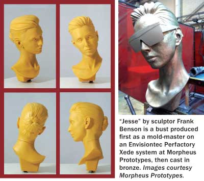 |
Zindroski says that although his company creates working parts for various industrial customers, much of his business involves organic sculpture- and art-based models, as well as toy models. For these applications, he likes the build speed and surface details of parts built on his Envisiontec Perfactory Xede to capture a model or character in its total integrity.
Envisiontec parts made from SI500 (an ABS-like photopolymer) can be painted for a final product/sample or used as patterns for tooling. The system’s continuous, layerless z-build technology produces a surface accuracy ranging from 0.002 in. to 0.0006 in. without visible layering lines.
“It’s a versatile machine for higher-accuracy surface models,” Zindroski explains, “where we go from industrial applications to art-based applications.” He adds that his biggest problem is helping users from the gaming and entertainment industries understand the nuances of ensuring proper part thickness or offsets when creating the 3D solid model.
Modern Metal Masters
The phrase “Old World craftsmanship” may not immediately bring to mind additive manufacturing techniques, but it does evoke attention to detail. At C&A Tool Engineering, those words capture a point of pride suggested by the company’s Swiss-chalet-like building architecture (in the middle of Indiana), and confirmed by the complex fuel-system, medical and aerospace components and tooling it produces. The phrase also aptly describes the capabilities of its EOS direct metal laser sintering (DMLS) systems.
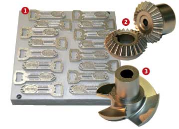 1: “Vintage Favors” are bottle openers produced on an EOS M270 system in stainless-steel 17-4 by C&A Tool Engineering. 2: C&A Tool Engineering produced this finely detailed set of beveled gears in cobalt chrome on an EOS M270 system. 3: C&A Tool Engineering produced this finely detailed impeller in cobalt chrome on an EOS M270 system. Images courtesy C&A Tool Engineering. |
C&A President Richard Conrow says that the need to produce exacting geometry drove him to supplement his traditional machining tools with the first of eventually three EOS systems. Added to the challenge is the fact that many of his customers are involved in R&D. Such groups are downright secretive about the reasoning behind their specifications, or just how the product will be used. The company must be ready to handle any requirement, whether geared toward a prototype or final part. Versatile EOS systems provide a critical advantage.
“Most of our customers are looking for something functional,” Conrow explains. “The degree of difficulty, quick turnaround time, size and weight all determine when using DMLS is appropriate. Many items absolutely cannot be machined.” He says the medical field uses this technology more than most, and much of that activity is because of advancements in materials. Typical DMLS parts include titanium acetabular shells and stainless steel surgical guides.
C&A Tool built an entire impeller, including blades, hub, keyway and bore, using DMLS—with every part complete, down to its final finish. The cost and performance were competitive with traditional casting and machining processes. Conrow says he believes not all customers realize that this approach can maintain tolerances of +/- 0.002 in., and that today’s systems produce fully dense parts.
The company also sees a strong role for DMLS technology in manufacturing tooling sets. The ability to create conformal cooling channels and rake angles offers critical improvements in tooling performance.
Conrow likens his metal-working specialty business to an art, and refers to C&A Tool’s employees as master craftsmen. The team recently completed a custom order for 30 class rings on the EOS systems, so it’s easy to believe.
Forming a Niche in Tooling
Sometimes the most successful companies start with an “aha” moment. When Jeff Ewert of Forming Solutions Inc. (FSI) was an engineering manager for a thermoforming company, he heard about the same problem over and over: The machine shops that made his prototypes lost production time whenever they had to clean aluminum residue out of the computed numerically controlled (CNC) machine to switch to using dense RenShape urethane foam. His light-bulb decision: set up a shop specializing in foam-type projects only, and avoid the cleaning problem altogether.
FSI’s rapid system of choice from Day One, back in 2004, was an MDX desktop milling machine from Roland DGA. Although capable of handling a wide variety of metals, woods and other materials, the company uses it strictly for non-metal products such as RenShape, nylon, urethane, epoxies and phenolic plastics.
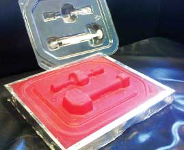 Forming Solutions Inc. (FSI) milled this medical prototype mold with snap-in components on a Roland MDX system. Material used was MB-4000 Urethane foundry board. FSI chose the Roland system for low-volume thermoform runs, producing good part clarity. The company ran 250 parts from this mold; more could be run without any problems. Image courtesy Forming Solutions Inc. |
The Roland system is so compact and self-contained, in the beginning Ewert took the equipment to trade shows and even to the customer, producing prototypes “on the doorstep.” Business success led him to open a permanent location called Forming Solutions. His former employer became his best customer, and his competitors started sending him their own foam jobs. Now FSI’s system runs almost non-stop “especially lights-out, unattended, at night.
Within the niche market of thermoforming, FSI creates prototypes from about 6 in. on all sides to larger than 18x20 in. Ewert has even created larger parts by rotating them through different spindle orientations or bonding smaller pieces. Because of the durability of the materials handled by the Roland system, some of his customers use the molds for actual production runs of 50 to 1,000 parts; others use them to confirm fit and function before committing to expensive hard tooling.
Ewert says the MDX equipment lets him create parts “almost in a production scenario “but no two are alike.” He points to the huge cost advantage of the Roland setup compared to that for a traditional CNC machine, or even to other desktop milling systems and adds, “I wanted the good name and quality.”
Steps in the Right Direction
Just as a building is only as good as its foundation, a new shoe design depends on all the right attributes of its sole. Determining the details of that design is one of the many jobs of Toby Ringdahl, CAD/technical development manager for global footwear product development at Timberland Boot Co.
Twelve years ago, Ringdahl managed the Timberland model shop, where two people devoted their time to hand-crafting elements of shoe models from wood, Bondo and filler materials.
“It was all just to see what the part would look like before we opened the mold, which was built overseas,” explains Ringdahl. “If it was incorrect, you’d start over again “and lose a lot of time plus the money.”
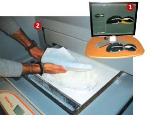 1: The completed shoe-sole prototype. |
It was a slow and expensive process for an industry that demands at least two complete product development cycles per year, and where naturally, Timberland wants to be first to market for any given style. Moving to laser-scanning of the handmade models and recreating them in CAD was the first step toward streamlining the design process.
In 2003, as a trial effort, Ringdahl started outsourcing 3D CAD designs to a service bureau running ZCorp 3D printers. Prototypes made on these powder-based systems were so accurate and insightful, by the end of the year he bought his own unit: a monochrome ZCorp 310 that immediately saw extensive use. In a single development season, his group may work on 20 to 24 sets of tools, printing several iterations each of outsoles and components to get everyone to agree on a shoe’s form, fit and function, from design to product management to engineering.
“That’s a lot of material we go through,” adds Ringdahl, who has since upgraded his equipment “first to a ZCorp 510 color machine, and most recently, to the more automated 650 model. He says they run almost every day, printing prototypes not just of the soles but also of the “lasts” “the forms over which leather is stretched to make the shoes. (Production lasts are CNC-machined from recyclable plastic.) Color, resolution, speed of operation, cost of materials and cost of operations have all made the ZCorp system the best choice for his group’s prototyping work, he says.
Contributing Editor Pamela Waterman, DE’s simulation expert, is an electrical engineer and freelance technical writer based in Arizona. You can send her e-mail to [email protected].
More Info
Subscribe to our FREE magazine, FREE email newsletters or both!
Latest News
About the Author
Pamela Waterman worked as Digital Engineering’s contributing editor for two decades. Contact her via .(JavaScript must be enabled to view this email address).
Follow DE

