Reverse Engineering 101
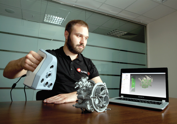
A hand-held Artec 3D Laser Scanner being used to create a CAD model of an existing part. Image courtesy of Artec 3D.


Latest News
September 1, 2015
 A hand-held Artec 3D scanner being used to create a CAD model of an existing part. Image courtesy of Artec 3D.
Reverse engineering is the process of studying a physical product in order to extract its design information with the intent to reproduce the product, or to create another object that can interact with it. In the past, designers had to physically measure the product to redraw the geometry. Today, designers can use 3D scanners to capture measurements. The scanned data can then be imported into CAD where the design can be processed, manipulated and refined. Designers, engineers, manufacturers and makers today are using 3D scanning and 3D modeling to retrofit designs, create third party add-ons, or to restore older products and designs. They are also using these techniques to create new products that interact with existing designs.
When is Reverse Engineering Useful?
Andrei Vakulenko, Artec 3D’s vice president of Business Development, presented several cases where one might need to reverse engineer something. He said that perhaps you have a situation where, “you have some kind of technical object, but, for various reasons, you don’t have the documentation for it or the mathematical model. For example, the object was made years ago when CAD was not used in the manufacturing and design industry. Or perhaps the manufacturer just did not provide the documentation. Or the documentation was lost.”
There are many reasons for the need to recreate an object. Vakulenko says that you may need to “recreate the object, either because you need the object itself or because you need to make something around the object for which you need its exact measurements.” He added that reverse engineering often involves modifying or recreating a pre-existing object.
The Reverse Engineering Process
Martin Chader, country general manager at Creaform, presented a paper at the SME RAPID 2008 conference on the value of third-generation parametric modeling from 3D scan data. His paper discusses using non-contact dimensional measurement tools such as 3D scanners for shape capture to assist with conceptual design models, to perform competitive analysis, document legacy parts and tooling, and to define the spatial constraints into which a new part must fit.
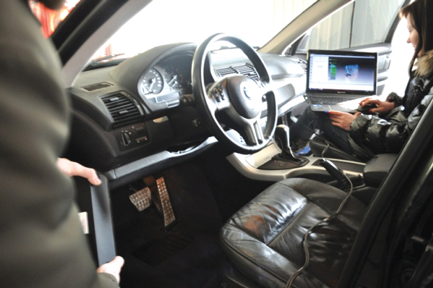 Nika Holding, a company that makes custom automobile accessories, preparing to scan the floor of a car to make custom floor mats. Image courtesy of Artec 3D.
“Each of these uses results in the capture of physical shape into a CAD model, often for further engineering,” he writes. Once the object has been scanned, the data collected can be manipulated in CAD software. The CAD designer uses the data as a template to create a NURB (non-uniform rational basis spline) or parametric model.
“Parametrics modeling is used for designing mechanical, simple geometric objects (objects that can be made up of cylinders, spheres, cuboids, etc.),” says Vakulenko. “NURBS is for making models of more complex, freeform objects—e.g. people—and uses curves and points to recreate the shapes.”
When Should Parametric Modeling Be Used?
Parametric or history-based modeling environments “require advanced planning of features, constraints, relations and dependencies within a model,” says Michael Kasten of Kasten Marine Design Inc. This method of 3D modeling in reverse engineering creates a “history of the logical genesis of the model.” This history is “maintained so that changing a pre-defined parameter changes the model,” he says. Once the parameters, or the parametrics, of a design have been set, the CAD model will interact with the scanned data appropriately.
In his paper, Chader stated one of the main reasons for using parametric modeling in reverse engineering projects: “If we anticipate any changes to the engineered part from its current form, or if we want to record and edit the part’s form in CAD, then parametric models are preferred,” he writes.
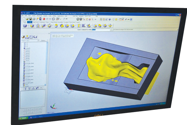
Kasten describes the process of scanning an automobile brake drum in order to reverse engineer it to improve it. He proposes that if analysis is done on the scanned object and a design change is required, then the engineer would not want to manipulate the scanned data nor would they want to alter a NURBS network. “The engineer will modify a single parameter in the CAD model,” writes Chader.
Parametric models are used when exact surfaces and parts are needed. They will often consist of multiple parts.
Implementing NURBS Surfacing
Shashank Alai, a former student at the Sandip Institute of Technology, wrote a paper for the International Journal of Emerging Technology and Advanced Engineering reviewing the use of 3D design parameterization in reverse engineering in which he described cases where using NURBS for CAD modeling was preferred. “Converting data points into NURBS surface models has been automated,” he writes. However, we cannot fully automate the conversion of 3D scanned data into parametric solids because “the original design intent embedded in the data points must be recovered and realized in the parametric solid model.
“Designers must be relieved from dealing with tedious point data manipulations and primitive geometric entity constructions,” Alai continues.
NURBS surfacing techniques would be employed when the design needs to be more organic and not dependent on exact design circumstances. NURBS designs are often made of one piece.
Why Not Choose Both?
There are some instances where a designer would want to use parametric and NURBS surface modeling for the same design. Ome example is a cellphone case. These types of coverings need to be exact on the inside to connect to the mobile device correctly. However, the outside of the design needs to fit the palm of a hand and may be modeled more easily using NURBS surfacing. The phone that is to be covered can be scanned and converted into a 3D CAD model where a parametric model is used. The outer surface of the case can be a NURBS surface.
 A CAD model of a scanned pad that forms around a wheelchair user leads to a finished mattress that fits the user’s body. Image courtesy of Artec 3D.
Kasten said that he prefers to use direct or free-form modeling environments when he designs. “They allow a more intuitive and flexible hands-on manipulation of the model regardless of how or in what sequence the model was created,” he says. “In many cases relationships can be defined, such as for trimming or to bond surfaces along an edge or to enforce tangency between surfaces, but they are not needed in order to create the model, and they do not affect one’s ability to grab parts of the model and push, pull, move, etc.”
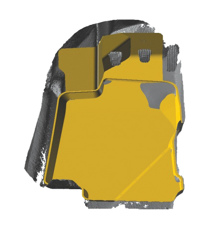 Nika Holding’s CAD model of the scanned car floor. Image courtesy of Artec 3D.
The most important steps in reverse engineering a product are “First, capturing the form of the object – i.e., 3D scanning it,” says Vakulenko. “Second, making the CAD model.” When deciding which type of CAD surface modeling technique to use one must consider the design intent. What are you trying to accomplish? Is it a free form, organic model or an exact and engineered device that may need to change?
More Info
Subscribe to our FREE magazine, FREE email newsletters or both!
Latest News
About the Author
Brian Benton is a freelance writer based in Florida. He writes the CAD-a-Blog website at cadablog.blogspot.com.
Follow DE

