

Latest News
December 4, 2001
By David Cohn
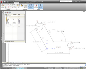 Figure 1: New parametric drawing tools let you define persistent relationships between objects. Parallel lines remain parallel and concentric circles remain centered. You can also define dimensional constraints that are driven by formulas based on relationships between objects. |
Powerful New Parametric Drawing Tools
Topping the list are powerful new parametric drawing tools that let users constrain drawings based on design intent. These new tools let you apply both geometric and dimensional constraints to ensure that specific relationships and measurements remain persistent even as the objects are modified. While similar tools form the basis of sketching environments in programs like Autodesk Inventor, this is the first time they’ve been available as native commands in AutoCAD. (Similar capabilities were available in AutoCAD 2008 via the IDX VCS plug-in, reviewed in the March issue of DE.)
Geometric constraints let you specify geometric relationships between objects. For example, you can specify that two lines remain perpendicular. With dimensional constraints, you can drive the size or spacing of objects as either explicit dimensions or as mathematical formulas. For example, you can change the distance between two parallel lines by entering a new value or specify that the length of an object is twice its width.
Tools for adding constraints are easy to use and conveniently located on a new Parametric ribbon bar. As you add geometric constraints to an object, each constraint appears on a constraint bar adjacent to that object. When you move your cursor over a constraint, its associated geometry is highlighted. Constraint bars can be moved or hidden. To remove a constraint, you just select and delete its icon from the constraint bar. AutoCAD 2010 supports 12 different types of geometric constraints: coincident, collinear, concentric, fix, parallel, perpendicular, horizontal, vertical, tangent, smooth, symmetric, and equal.
You can also significantly automate the process of applying constraints using the Auto Constrain tool. Auto Constrain applies constraints to selected geometry that falls within specified tolerances. For example, if you select a rectangle, Auto Constrain generates appropriate coincident, horizontal, parallel, and perpendicular constraints.
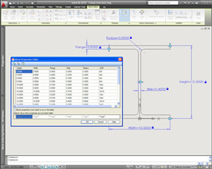 Figure 2: Constraints also enhance dynamic block creation. The updated block-editing environment includes all of the geometric and dimensional constraint tools plus a new Block Table tool that lets you establish lists of preset dimension values. |
Dimensional constraints put limits on measurements of geometry. AutoCAD 2010 supports seven types of dimensional constraints—linear, aligned, horizontal, vertical, angular, radial, and diameter—similar to the different kinds of dimensions. Dimensional constraints can be displayed as a name, a value, or an expression. A small lock icon appears adjacent to dimensional constraints to help differentiate them from regular dimensions. Like geometric constraints, dimensional constraints can be easily moved, hidden, or deleted.
A Parameters Manager palette displays the name, expression, and value of all dimensional constraints in the drawing. You can easily change values, rename parameters, replace values with formulas based on those parameters, delete constraints, and add user-defined variables. You can also convert existing dimensions into dimensional constraints. Additionally, you can control whether a dimensional constraint is annotational or dynamic. Dynamic dimensional constraints resize as you zoom so they are always readable; they are not intended for use as plotted annotations. Annotational constraints, however, are meant to be plotted. They look just like dimension objects, with their appearance controlled using styles.
Dynamic blocks get better
The new constraint tools have also been extended to AutoCAD’s dynamic block editor. Dynamic blocks, which were added in AutoCAD 2006, enable a single block object to have multiple variations. But creating dynamic blocks with complex behaviors has been quite challenging. Being able to use constraints within the block editor changes that.
In AutoCAD 2010, the block editor environment includes many of the same geometric and dimensional constraint tools found in the regular drawing window. Constraints created while working within the block editor apply to the block definition. They are similar to action parameters used in previous versions of AutoCAD, but are much easier to understand and manipulate. In addition, a new Block Table tool lets you set up a list of preset values for each dimensional parameter in a dynamic block. While you can fill out the table manually, you can also paste values from a spreadsheet or text file. Once established, you can quickly change the entire block by making a single selection from the table.
Also new is a Test Block window. In previous versions, to test dynamic block behavior, you’d have to save your changes, insert an instance of the dynamic block into your drawing, and then see if the block behaved as expected. The result was lots of trial and error. But the Test Block tool in AutoCAD 2010 lets you verify behavior of the dynamic block within the block editor environment before saving changes.
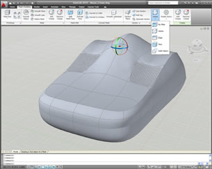 Figure 3: AutoCAD’s new mesh modeling tools make it easy to create smooth, organic shapes. You can add mesh complexity in specific areas where more detail is required, and use improved gizmos to manipulate objects in 3D, with filters to help select specific sub objects. |
Organic 3D Modeling
While the parametric design tools only work in 2D, there are lots of exciting 3D enhancements in AutoCAD 2010 as well. The biggest is a new set of subdivision surface modeling tools. Although AutoCAD 2007 introduced some pretty robust modeling tools, creating objects with smooth surfaces and organic characteristics remained difficult. AutoCAD 2010 changes that with the introduction of a new mesh object. Tools on the new Mesh Modeling ribbon tab let you create primitive mesh shapes such as boxes, cones, cylinders, and wedges as well as revolved, ruled, and other types of mesh surfaces.
Unlike solids, faces of mesh objects are divided into smaller faces based on mesh tessellation values. Users can control the default tessellation divisions for each type of primitive as well as the behavior for converting objects such as solids and surfaces into meshes.
Once created, another set of tools let you incrementally increase the smoothness of a mesh. You can also convert existing 3D solids, 3D surfaces, 3D faces, polygon meshes, polyface meshes, regions, and closed polylines into mesh objects using the new Smooth Object tool. Even after you’ve created a mesh object at a specified smoothness, you can easily increase or decrease its smoothness, including being able to confine the mesh complexity to areas where more detail is required. You can also control the behavior of sub objects within a mesh using the new Crease tool, so that objects are unaffected by mesh smoothness along those edges.
Additional mesh editing tools let you split a mesh face and extrude faces to deform the mesh object. After using the various mesh tools to create organic shapes, you can convert meshes to smooth or faceted solids or surfaces, with control over the smoothness of objects during the conversion process.
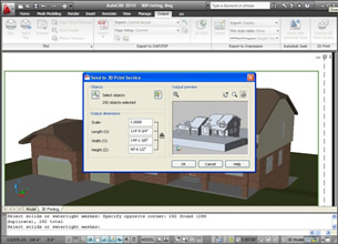 Figure 4: 3D printing capabilities make it easy for users to produce physical 3D models and prototypes by connecting directly to 3D printing service providers. |
To help you manipulate objects in 3D space, AutoCAD 2010 also includes a new 3D Scale gizmo in addition to the 3D Move and 3D Rotate gizmos that first appeared in AutoCAD 2007. Using these interface tools, you can move, rotate, or scale selected 3D objects within the constraints of a specified axis or plane. If you right-click when a gizmo is visible, a new context menu lets you change the gizmo’s behavior. As in previous releases, you can hold down the Ctrl key to select sub objects such as an edge, face, or vertex. But now, you can also apply sub object selection filters to ensure you select the type of sub object you expected.
Drafting Enhancements
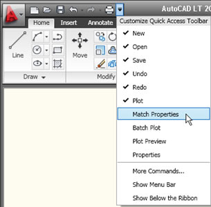
In addition to these big changes, AutoCAD 2010 has a bunch of less spectacular but equally useful alterations and additions, beginning with a new initial setup wizard that helps tailor each user’s installation based on industry, workspace, and drawing preferences. The application menu has also been streamlined, and while that means you’ll no longer find the old pull-down menus hidden there, users can still switch back to the AutoCAD Classic workspace with menus and toolbars. But after working with AutoCAD’s ribbon bars for more than a year, many users now prefer them. The Quick Access toolbar has also been enhanced, including new options to make it easier to add and remove tools from the toolbar.
More Information Pricing: System Requirements |
The new release also offers significant enhancements to AutoCAD’s PDF support, including both better PDF output and the ability to attach a PDF file to a drawing as an underlay. There’s also a new Reverse command that lets you reverse the direction of lines, polylines, splines, and helixes. A new MeasureGeom tool replaces the old Measure command. Various options let you measure distance, radius, angle, area, and volume much more intuitively than in the past, with area and volume highlighted in the drawing as you work so you can easily see what you’re measuring.
3D Printing, which first appeared as an add-on to AutoCAD 2009, is now built in to AutoCAD 2010. This simple utility walks you through the steps of preparing your model, creating an STL file, and then sending the file via the Internet to a user-specified vendor for printing. The final 3D model is then produced and shipped back to you within days. Prices are based on the solid volume of the model and range from $15 to $25 per cubic inch.
All these new tools are bolstered by a number of other improvements. For example, externally referenced objects can now be grayed-out, with easy control over the amount of fading. When applying a hatch pattern, if a valid hatch boundary is not found, AutoCAD now attempts to show you where the problem might have occurred. Red circles appear around endpoints near where the software detects a gap in geometry.
An updated Splinedit command includes an option to convert a spline into a polyline. The Purge command has been updated to include an option for purging zero-length geometry and empty text objects. You can now control the rotation of a view within a layout viewport, attach externally referenced files using geographic data, and save drawing files larger than 256MB.
Speaking of file size, AutoCAD 2010 brings with it a new DWG file format. While the software can open drawings saved in earlier versions, anyone needing to share drawings with someone using an older release will need to specifically save in the older format. The CUI files used to save user interface customization have also been replaced by a new CUIx file format.
I’m not sure how they manage to do it year after year, but Autodesk’s programmers have done it again. AutoCAD 2010 looks to be the best one yet.
AutoCAD LT, AutoCAD’s lower-cost 2D drafting sibling, has once again adopted some of the new features of Autodesk’s flagship program. And this time around a number of features formerly found only in AutoCAD itself have trickled down. AutoCAD LT users will likely applaud the inclusion of the same PDF underlay and improved PDF output capabilities added to AutoCAD 2010. Users can work with PDF underlays in the same way they work with other external references, and in fact, external reference commands formerly found only in AutoCAD, such as in-place reference editing, are now available to LT users. They can also now clip an external reference and control the clipping boundaries. Other new LT capabilities previously available only in AutoCAD include the ability to synchronize attributes to update all instances of a block when new attributes are added to block definitions and an enhanced attribute editor for changing the properties of individual attributes. LT also finally acquires AutoCAD’s Align command. Other than that, the changes in AutoCAD LT 2010 shadow those in AutoCAD itself, including an updated ribbon bar, enhanced Quick Access toolbar, and streamlined Application menu. And like AutoCAD 2010, AutoCAD LT 2010 uses an updated DWG file format, so if you work with people using an older version, you’ll need to use the SaveAs function to save to the previous DWG format. What AutoCAD LT doesn’t get is any of the new parametric drawing or cool 3D modeling features. LT remains strictly 2D, although it can display 3D models created in AutoCAD. Yet in spite of its limitations, AutoCAD LT remains the top-selling 2D drafting and detailing product. For those who need full DWG native file format compatibility but can live without AutoCAD’s more advanced tools and capabilities, AutoCAD LT continues to offer much of what you get in AutoCAD, at a fraction of the cost.—D.C. |
Contributing Editor David Cohn is a computer consultant and technical writer based in Bellingham, WA, and has been benchmarking PCs since 1984. He’s the former Editor-in-Chief of Engineering Automation Report and CADCAMNet, and the author of more than a dozen books. Please send comments about this article to [email protected]. You can also contact David at [email protected].
Subscribe to our FREE magazine, FREE email newsletters or both!
Latest News
About the Author
David Cohn is a consultant and technical writer based in Bellingham, WA, and has been benchmarking PCs since 1984. He is a Contributing Editor to Digital Engineering, the former senior content manager at 4D Technologies, and the author of more than a dozen books. Email at [email protected] or visit his website at www.dscohn.com.
Follow DE

