Review: Solid Edge with Synchronous Technology 4
Solid Edge with Synchronous Technology 4 shifts the focus from form creation to productivity, assembly management and advanced analysis.


Latest News
September 1, 2011
By Kenneth Wong
In the third release of Solid Edge with Synchronous Technology (SE with ST3) from Siemens PLM Software, the software took a major step (one small step in programming, one giant leap for CAD): It managed to consolidate history-free modeling and history-based modeling into a single environment. In Siemens PLM Software’s lingo, history-free modeling—creating geometry via push-pull action with little or no regard for feature history—is called Synchronous. Its older cousin, history-based modeling, is called Ordered. The ability to move features from Ordered to Synchronous, then back to Ordered if one wishes, was a milestone, not just in the brief history of SE with ST, but in the history of CAD.
SE with ST4, which debuted in a global launch event in May, introduces a number of noteworthy interface refinements, assembly management tools, and analysis functions to the software. They’re not milestones in themselves (it would be unrealistic to expect every release to be a milestone), but they add up to improved productivity.
For the Visual Creatures Among Us
Now that multi-core CPUs and GPUs have pumped up graphics processing in standard CAD workstations, many CAD software packages are taking advantage of the added horsepower. Autodesk Inventor 2012, for example, gives you the option to work with models in a photorealistic mode, complete with ray-tracing and reflections in high dynamic range (HDR) images. SE with ST3 gives you the option to work with ground plane reflections and shadows.
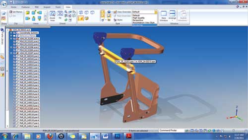
SE with ST4 lets you work with richer graphics—complete with ground
plane reflections and shadows.
If you’d like to work in a more graphics-rich environment, you may choose High Quality or Rendering, available in a dropdown window under the View tab. It also gives you the option to set the sharpness of your display, from levels 1 to 5. The higher the level, the better the contrast. However, bear in mind that a higher setting requires more computing time, so your system response will noticeably slow down if you don’t have a machine powerful enough to compensate for its demand.
SE with ST4 does not give you the option to work in ray-traced mode. Rather, if you’d like to produce a photorealistic, ray-traced look of your design, you can get into the Explode, Render, Animate (ERA) mode under the Tools tab to render your scene. You can render the entire scene, or just a portion of it by window-selecting the area you want to render.
Revolution in Navigation
One of the most effective uses of the steering wheel control in SE with ST4 is the ability to use its rotation circle to execute the Revolve command.
Suppose you have a 2D profile you need to revolve 360 ° to create a solid. You may choose the Revolve command in the menu, as you would normally do. But, bypassing the menu altogether, you may also align the control’s rotation point to an axis at the base (or top, as the case may be) of the 2D profile and click on the wheel. This activates the Revolve command automatically (you’ll see the Revolve icon appear in the input bar). Now, all you need to do is enter the desired degree of rotation to complete the command.
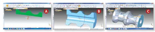
Using the steering wheel, you can instantly execute a Revolve on a 2D
profile (A, B). The resulting solid contains a nested 2D cross-section, available
for dimension-driven edits (C).
The use of this command automatically creates a 2D cross-sectional plane nested inside your solid. This 2D cross-section can be edited, much like a dimension-driven sketch. The numeric changes you make will be reflected in the solid part created from it.
Directing your Copy
In assembly mode, placement of copied parts gets easier because you can now use the steering wheel to position your copied parts.
Suppose you need to place two caps at both ends of a pipe. You may select the cap on one end, position the steering wheel to the midpoint of the pipe, then steer a copy of the cap to travel along a perfect arc in 180 °, ending at the opposite end of the pipe. Upon executing this command, ST4 will seek out and identify logical relationships based on what’s in the initial cap (mated faces and aligned axes, for example). Then, ST4 will prompt you with a choice to suppress the existing relationships, repair them or accept them as transferred to the new position.
Going on a Tangent
The new release gives you an easier way to place holes on cylindrical objects, such as shafts. It lets you drag holes along the circular surface on a tangent, which eliminates accidentally placing holes misaligned with the center axis of your cylindrical objects. If your design already consists of a nested 2D cross-section (like the revolved solid mentioned above), you’ll see the 2D profile updated, with the cutout corresponding to your holes once you complete the command.
Facing Relationship Hiccups
In SE with ST4, you can use the Face Relate tab to automatically build relationships between faces that don’t have any correlations.
For instance, you may select several faces tilted at different angles, then select the Parallel option to force them to align themselves as parallel surfaces. If you want this relationship to persist, you can choose the Parallel Persist option—essentially instructing the software to retain the parallelism during subsequent modifications.
While the concept is simple, the process seems (at least to me) more complex than necessary. The series of options you need to select is not always easy to grasp. To make the parallel execution possible, you’ll have to pick the appropriate choices for extend/trim treatment, model/set priority, and single/multiple alignment. If you have a pair of faces, the relationship seems simple enough. But if you have more than one face, the order in which you select the faces affects how the alignment is performed.
At times, face relationships may also come in conflict with ST4’s built-in Live Rules (the set of rules that define how features and faces align with one another during your push-pull operations). In some instances, you may need to cancel or suspend Live Rules before the desired face relationship can be established.
In my view, a simpler implementation of this function may serve its purpose better.
Mid-plane Drifters and Framers
In Simulation mode, SE with ST4 gives you the option to analyze designs using mid-planes only—a handy feature for those working closely with sheet-metal parts and solid parts with flat features. When opening a part suitable for mid-plane analysis, the mid-surface generator lets you create a 2D surface of your flat (sheet metal-like) feature by offsetting from a chosen face (outer or inner). With the mid-surface in place, you may apply forces, define pressure, fix points, then mesh and solve the analysis scenario. The resulting deformation, stress distribution and displacement are available for output in animation, along with numeric values.
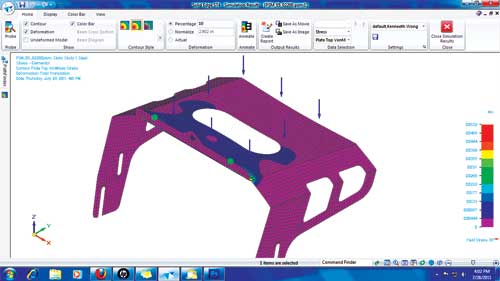
In Simulation mode, you can use mid-surface analysis function to simplify
meshing and solving of sheet metal-like parts.
Similarly, you can now use single straight lines to represent frame structures for analysis. When conducting stress tests on frame assemblies, you’ll see Beam as one of the meshing options available. The function allows you to reduce 3D structural frames into 1D lines with nested volume and material information. In giving you the option to represent plate-like features as flat surfaces or frames as straight lines in analysis, SE with ST4 simplifies the meshing and solving process “leading to quicker results without a compromise in accuracy. For those who have a better understanding of meshing, SE with ST4 gives the option to specify the mesh-map profile to use.
In Simulation mode, you can override or temporarily suspend material and volume definitions in your parts. With this option, you may, for instance, run analysis on a part originally specified as steel at 3-in. thick as if it were an iron part at 4-in. thick. The quick, flexible approach lets you try out different materials and volumes in stress analyses, without the need to change part geometry or create multiple versions of the same part.
Other Improvements
In drawings, if you have a table (say, a bill of materials) with a stack of cells populated by identical numeric values, you may now combine them into a single cell block for a cleaner look. In creating exploded views, you can now manually draw flow lines to get better control over how they look.
From Conceptual Design to Production
With a novel take on history-free modeling, the debut of SE with ST forced many of its competitors to re-examine their own code. Many CAD programs now incorporate some versions of history-free push-pull editing, fundamentally changing the trajectory of mechanical CAD.
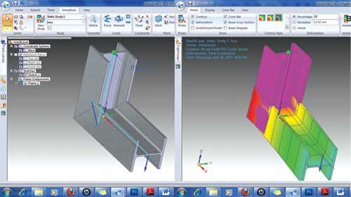
A new mesh type, Beam element, lets you simplify structural frames and
beams into single lines, with nested volume and material information.
In SE with ST4, a workflow that combines ordered (parametric) and unordered (history-free) modeling continues. But R&D efforts in ST4 reflect an effort to move beyond the wow factor, to settle on a more thoughtful, efficient interface for part modeling and assembly management.
Simulation tools in previous versions of SE with ST were robust enough for basic linear stress analysis. The addition of mid-surface analysis and beam-element analysis advances its reach. SE with ST’s initial claim to fame may have been easy geometry creation, experimentation and conceptual design. Refinements in SE with ST4 show maturity—a sign that the software is ready to take its rightful place in production-grade work.
For More Information:
Kenneth Wong writes about technology, its innovative use, and its implications. One of DE’s MCAD/PLM experts, he has written for numerous technology magazines and writes DE’s Virtual Desktop blog at deskeng.com/virtual_desktop.com.
Subscribe to our FREE magazine, FREE email newsletters or both!
Latest News
About the Author
Kenneth Wong is Digital Engineering’s resident blogger and senior editor. Email him at [email protected] or share your thoughts on this article at digitaleng.news/facebook.
Follow DE

