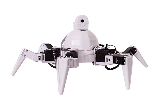
EZ Robot built a robot platform using Blender and Altium Designer. Image courtesy of EZ Robot.


Latest News
June 1, 2015
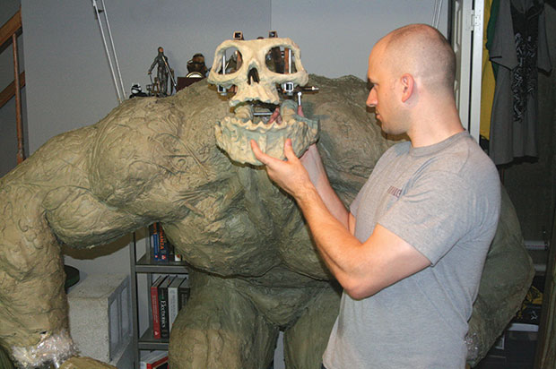 Roboticist Derek Scherer used both the SolidWorks and Linkage tools when designing his Brute Golem, pictured here with the Brute Golem skull idea. Image courtesy of Derek Scherer, Robot & Automation engineer, The Golem Group LLC.
Roboticists, especially those operating in small shops, are free to engineer their designs using the most suitable tools on the market—many of which come in free versions that will do the job without requiring a premium version.
The techniques and processes roboticists employ to bring projects that are both electrical and mechanical to life are as important as the tools they choose. While the design process can appear to be linear, new considerations can crop up at every turn that the roboticist must then input back into the design—perhaps at the very beginning.
Robot Design Tools & Techniques: Mechanical
As a sculptor chooses his own tools, so a roboticist selects his own design platforms. “I use SolidWorks daily for solid modeling. Such mechanical CAD tools are essential for designing systems that are as complex as most robots,” says Derek Scherer, Robot & Automation engineer, The Golem Group LLC, who designed robotics for the movies: “The Hobbit: An Unexpected Journey”, “Man of Steel” and “Elysium.”
SolidWorks brings a deep dimensional and mechanical understanding of surfaces to bear on robot projects. When a desktop engineer cuts a sphere in half in SolidWorks, this platform has the same realization that a human being has of the qualities and characteristics of half a sphere in a 3D space. “SolidWorks produces diagrams, tolerances—everything a shop would need to fabricate the resulting design,” says Scherer.
Another tool, Linkage, is a mechanical simulator that enables the user to create links and their connections and move parts inside the simulation to see how these operate collectively. “It’s useful in uncovering major design flaws early on,” says Scherer.
RobotsLAB, makers of RobotsLAB BOX educational robots uses Autodesk Inventor to design robotic mechanisms. While the capabilities of this design tool are many, the designer must still factor in the limits of fabrication technologies.
“If you want to cut the part out of metal, you have to keep in mind whether the cutter bit can make holes only in one size or can drill a hole on the underside of the part,” says Ryan Wood, lead engineer, RobotsLAB. Each building material will have its own fabrication limits.
Blender, a popular physics animation tool, is a popular choice for animation demonstrations and it’s free. “Whenever you see a robot animated on YouTube or a company website, chances are that they are using Blender,” says DJ Sures, president of EZ-Robot, maker of personal and educational robot platforms.
Blender is a 3D CAD design package that enables the engineer to load design files, animate any design, add effects and visualize robot projects. “Blender uses real physics with animations to simulate your robot so you can verify that it operates as expected,” says Sures.
Component Tips
RobotsLAB uses Autodesk Inventor to model components that it doesn’t build. When considering how to use a sensor or motor to purchase for their robots, designers will bring a model of that into CAD software to determine its placement and to consider how to place parts and equipment around it. Some companies provide CAD models of the parts they sell. “But we may have to use a mechanical drawing of a unit to model it in our CAD software. Or, we may purchase the part and create a model from that,” says RobotLAB’s Wood.
If a motor or other component takes up too much space on the robot, a roboticist might try to re-design the other components or the enclosure that everything fits into, or they may try to select a motor in a smaller size, according to Wood. But these component and design choices affect the robot and its capabilities, too.
Integrating Electronics
EZ-Robot, maker of personal and educational robot platforms, uses Altium Designer from Altium’s line of PCB (printed circuit board) design products. “I’ve used some of the free PCB design tools ... but there aren’t a lot of free tools that are very good because the paid versions include lots of design samples and templates that the free versions don’t,” says Sures.
Ben Wirz, president of Element Products, uses the schematic capture tool DxDesigner and the PADS PCB design tool, both from Mentor Graphics. A typical project using these tools starts with a specification to follow.
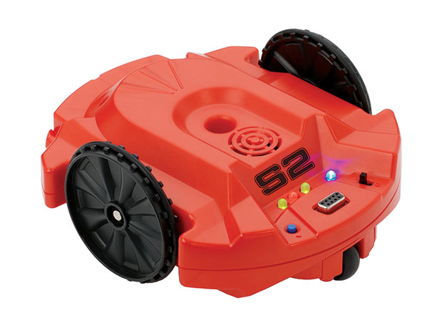 Ben Wirz used DxDesigner and PADS to design the S2 Scribbler Robot. Image courtesy of Parallax.
The design flow starts with a paper design, using spreadsheets, says Wirz. In fact, Microsoft Excel is one of Wirz’s most valuable electronics design tools. “I use it to do all the design equations, to calculate the resistor values and capacitor values and to work through all the theoretical calculations,” says Wirz.
Microsoft Excel enables Wirz to easily document the electronics design process as design choices change, such as can happen with the ambient operating temperature specification. “If a customer says: ‘We told you we wanted to work at 30°C, but we want to work at 20°C’, I can change the number in Excel and see how this affects the design,” says Wirz.
Wirz does the theoretical design and the mathematical design equations for engineering the circuit and enters the circuit into a schematic capture tool to add the transistors, resistors, and captures. “I make the circuit in DxDesigner, which connects all the pins together,” says Wirz.
The Mentor Graphics HyperLynx Analog add-on software that works with DxDesigner Schematic Capture Software comes in handy at this point for simulations. “It lets me do electrical simulations of the circuitry I design. I can simulate analog circuits with it. I find it useful when doing any sort of analog design or filter design,” says Wirz.
“Then I export it into the PCB tool to turn the theoretical into the physical, designing the circuit board and determining where the chips and components go down,” says Wirz.
Once the circuit board is designed, the desktop engineer will want to integrate the board with the mechanical design. “For that I export the PCB design to Creo, a mechanical 3D design package from PTC,” says Wirz. Creo enables the engineer to have a physical object to integrate with the robotics design.
“I can make a 3D model of an enclosure and print it out on my 3D printer to check that my circuit boards fit,” he says.
 EZ Robot built a robot platform using Blender and Altium Designer. Image courtesy of EZ Robot.
Design Considerations
RobotsLAB designers consider the whole robot system, its electronic, computerized and mechanical aspects together and how these affect each other when designing within any of those areas.
“Say you need a robotic arm to pick up a 2-lb. weight. The gripper you design weighs a certain amount too. The base joint of the arm now needs to lift the weight as well as the weight of the arm and gripper. This leads us to question the power abilities of the electronics,” says Wood.
More powerful electronics may be necessary if the performance of the robot requires more energy than the electrical specifications support, and to avoid power supply failure, for the safety of others in the robot’s environment.
Similarly, to give the end effector more gripping strength, the roboticist may have to consider larger, more powerful gripper motors. Those motors could necessitate stronger motors in the rest of the arm to lift that extra weight, which could again lead to reconsidering which electronics could support the design.
As each robot project is unique and fluid, so too is a roboticist’s choice of tools.
More Info
Subscribe to our FREE magazine, FREE email newsletters or both!
Latest News
About the Author
DE’s editors contribute news and new product announcements to Digital Engineering.
Press releases may be sent to them via [email protected].
Related Topics


