
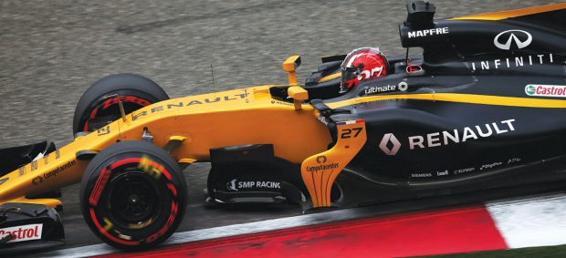
Renault uses Elysium’s CAD translation technology to prevent data loss in converting legacy data. Image courtesy of Elysium.


October 1, 2017
 Renault uses Elysium’s CAD translation technology to prevent data loss in converting legacy data. Image courtesy of Elysium.
In the 21st century, as technology became the driving force behind the race cars, more rules were adopted to curb or prohibit techniques that might jeopardize the race’s safety. In 2011, “to reduce the speed of Formula One cars and to facilitate overtaking, the double diffusers used since 2009 and the F-ducts developed in 2010 are prohibited,” for example.
But the temptation to find regulatory loopholes to outwit the system proved irresistible. The engineers’ quest to find strategic advantages without violation, and the regulatory body’s attempts to restrict them became a game of cat and mouse. “But one innovation that has been actively endorsed is the DRS (drag reduction system) rear wing,” according to FIA.
In the 1960s, F1 cars began to sprout wings. The airfoils operate like aircraft wings, but in reverse. Whereas airplanes use their wings to create lift, race cars use theirs to create negative lift, or downforce. “The most obvious aerodynamic devices on a Formula One car are the front and rear wings, which together account for around 60% of overall downforce (with the floor responsible for the majority of the rest),” FIA explains.
For most F1 engineers, the race begins long before the car’s tires touch the track. Their quest for aerodynamic advantages begins in computational fluid dynamics (CFD) programs and wind tunnel tests.
Growing Model Size
Andy Wade, lead application engineer, ANSYS, has been a CFD software specialist for more than a decade. In 2006, ANSYS Software acquired Fluent, the CFD firm where Wade was working. As a result, ANSYS inherited not just Fluent talents like Wade but also the F1 teams using Fluent CFD tools.
“F1 teams often employ CFD at the very forefront of the design cycle,” says Wade. “For example, they may look at the shape of their airfoil and front wing as 2D geometry.”
It’s more than the airfoils. According to FIA, “Every single surface of a modern Formula One car, from the shape of the suspension links to that of the driver’s helmet—has its aerodynamic effects considered. This is because disrupted air, where the flow separates from the body, creates turbulence, which in turn creates drag and slows the car down.”
In the time Wade has been working in CFD, he’s seen the F1 teams’ model sizes getting bigger. “About 10 to 12 years ago, when everyone else was looking at models with five to 10 million meshes, the F1 teams were looking at models with roughly 50 million cells. Today, the typical F1 model size is 200 to 400 million cells—could even be a billion,” he notes.
“The airflow around F1 cars is very complex,” says Craig Skinner, deputy head of aerodynamics, Red Bull Racing. “CFD gives us a complete picture of the flow physics around a car. So after running CFD on a different geometry and seeing the results, we might go down a different design development path.”
Pushing CFD to the Limit
Generally, CFD users are willing to make a compromise between job complexity (or fidelity, as some might call it) and speed. Users who employ highly detailed models to simulate a series of time steps (that is, the aerodynamics of an operating vehicle over a specific period) accept the fact that such a job requires a longer period to process. If they want to get the answer back faster, they may choose to simplify the job (in other words, run the job in lower fidelity) by using a lower-resolution mesh model. But, not so with F1 teams.
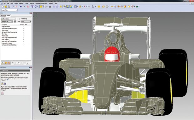 Elysium’s CADdoctor software lets you convert 3D data. The tool is used by the Renault F1 team. Images courtesy of Elysium.
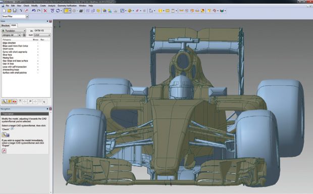 “Formula One puts more stress on CFD than anybody else we know,” says Steve Legensky, general manager and founder, Intelligent Light. “We work with NASA, Boeing, Lockheed and the Department of Energy. But F1 demands daily turnaround on multibillion-cell models to understand the smallest design details or the impact of weather. They want both fidelity and speed to decisions that impact the next race.”
The role of FieldView, Intelligent Light’s CFD post-processing software, is “from when the solver run ends to when the engineer makes a decision,” says Legensky. The software focuses on reducing the movement of results files which, in the case of F1 teams, could be massive. In minimizing data movement, it increases the CFD solution’s performance and nimbleness. The software also emphasizes “data management, allowing small packages of data to replace large results files while maintaining full numerical fidelity,” the company explains.
“Suppose a team wants to know the differences in the results between two different CFD runs with slightly different design geometry. FieldView can quickly subtract one run from the other, and show you the precise difference, both in numerical output and in images of the flow fields around the vehicle,” says Legensky.
Balancing CFD and Wind Tunnel
The FIA has set some strict guidelines on the use of CFD and wind tunnel testing. Simply put, the teams must ensure their combined use of wind tunnel testing (measured in wind-on time, or the time wind is blowing) and CFD usage (measured in teraFLOPS) remain within the allotted quota.
“We have to split that quota between CFD and wind tunnel,” says Skinner. “We have to decide if we want to run a full-car model or a sub-car model; what type of turbulent model to use; whether we want to use transient calculation and so on. We have to find a way to get the best results using the least amount of teraFLOPS.”
This is a dilemma because CFD is particularly compute-intensive. “Most teams would like to run transient analysis, because it gives them a lot more insights about the eddy and the flows,” says Wade. “But a transient state CFD job may take more than 100 times the CPU power than a steady state calculation. So the teams tend to do a mix of steady state and transient simulations.”
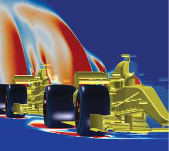 CFD simulation results show only the front car drives into undisturbed air. Simulation created in FieldView by Torbjörn Larsson, Creo Dynamics AB. Image courtesy of Intelligent Light.
“It comes down to a tradeoff,” explains Legensky. “If they want to do a lot of CFD, they have to do less wind tunnel testing and vice versa. So the teams have to be extremely clever. The rules specify what constitutes usage of CFD. For example, if you do CFD calculations on vehicle models that are older, it’s not counted against that balance.”
A team can preserve its CFD allocation balance by performing simulation using older vehicle models. But this approach has certain disadvantages. For one, the results obtained with older vehicle models and track data won’t accurately portray how the current vehicle will behave on the current track. Furthermore, the CFD job still requires considerable time and effort to prepare and set up, and costly hardware to process. The resources may be better spent analyzing the most current vehicle.
“One thing to note—the work done in post-processing is not counted against your balance,” says Legensky. “So we help our F1 customers move some of the analysis tasks out of the solver time, into the post-processing phase in FieldView and engineers can perform more high-value solver runs.”
Pixels vs. Wind
Wind tunnel test—placing a scale model of the vehicle and blowing air on it to observe the airflow—is a classic engineering tool. It’s part of the automotive and aerospace engineering workflow. CFD, by contrast, allows you to digitally create the airflow around the vehicle using 3D mesh models. So the wind tunnel test could, in fact, be replicated in pixels using CFD.
When Gaétan Didier, head of CFD for Sahara Force India, first joined the team, they relied more on wind tunnel testing and less on CFD. At the time, the CFD talent was “marginal,” he recalls. Wind tunnel test is “real physics, real airflow,” he points out. “But it can only show you wind blowing across a car. It won’t show you, for example, the airflow of a car turning a corner. In the wind tunnel test, the air is blowing straight in the working section. On the track in corners, the wind is coming in a curved fashion. Moreover, in CFD, you can simulate the brake cooling and radiator cooling activities, and exhaust pipe hot gas emissions, which you cannot simulate in the wind tunnel. So we use CFD to study that.”
In theory, other more sophisticated scenarios might also be analyzed in CFD: for example, the consequences of one car following another. In reality, however, setting up such a scenario could be problematic. “You cannot easily get the boundary conditions for simulating that scenario,” says Didier. “You don’t, for instance, have the geometry for the car in the front.”
The expertise making up Sahara Force India has shifted under Didier’s department guidance. Now, the talent pool is nearly evenly split: 50% wind tunnel experts, 50% CFD experts. “Our development has now become much more CFD-biased,” says Didier.
Though CFD is a computer model, the application is most useful for studying certain real-world phenomenons that are seemingly inexplicable. “We use driver feedback to understand where in the course he’s having issues,” explains Red Bull’s Skinner. “If he’s complaining about having problems with a particular corner—a low-speed corner or a high-speed corner—and we can’t see the problem in our wind tunnel data, we will create a specific CFD run to replicate the conditions on the track to understand his problem.”
The Optimization Challenge
The two critical parameters for F1 teams in CFD are downforce and drag. “F1 aerodynamicists have two primary concerns: the creation of downforce, to help push the car’s tires onto the track and improve cornering forces; and the minimization of drag, a product of air resistance, which acts to slow the car down,” according to FIA.
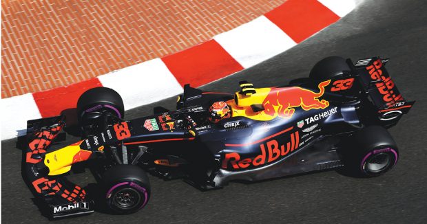 Red Bull Racing, like all other Formula One teams, must balance the use of computational fluid dynamics (CFD) and wind tunnel tests to remain within the allotted limits. Photo by Mark Thompson/Getty Images; Image courtesy of Red Bull Racing.
CFD optimization is ultimately striking a good balance between the two to create the most advantageous driving experience. “If you reduce drag all the way, the car will be flying off the track because there’s not enough downforce to keep it on the track,” says Legensky. “On the other hand, if (you) have too much downforce, your car runs too slow. So the F1 teams tend to optimize the downforce-drag ratio for all the different turns, hills and corners on the current track. Then they optimize it across all the tracks they’ll compete on for the entire racing season. It’s quite a fascinating optimization problem.”
Data and Translation
In 2002, when automaker Renault decided to get involved in F1, it acquired the Benetton F1 team. At the time, engineers decided to move to a new CAD software package, Dassault Systèmes’ CATIA. The challenge to convert legacy 3D CAD data into a format readable and editable in CATIA was significant. The project was the beginning of Renault’s partnership with Elysium, a company that specializes in data translation.
“Usually converting CAD files through some other neutral format might cause problems, like gaps in geometry and inaccurate or even missing entities,” says Annalise Suzuki, director of Technology & Engagement, Elysium. “The difference with Elysium is, we understand those conversations very well. What can take eight hours for someone to prepare and create can be done in minutes with our software.”
“The first component to be translated to CATIA was a complete gearbox,” recalls Patrick Sergent, Elysium’s Europe engagement lead. “The engineers were spending so much time having problems with translation that they came to us through another partner and finally, in just a few hours, the problems were solved.”
The Renault team uses CADdoctor, Elysium’s desktop CAD conversion software. “We are currently working with Elysium to implement an automated export process to allow our CAM (computer-aided manufacturing) users to easily transfer CAD data to some new machine tool controllers for NC programming,” says Mick Bennett, Renault team’s CAD/PDM (product data management) manager.
Al Peasland, head of technical partnership, Red Bull Racing, says, “The real challenge for engineering is the pace of change, and just how quickly we have to develop the F1 car to meet the demanding calendar we race in ... that requires a certain amount of skills, tools and infrastructure ... we work up to the shipping deadline.”
Red Bull Racing uses Siemens PLM Software’s NX software (for design and simulation) and Teamcenter (for data management) to keep track of its “five complete sets of track equipment; 21 races across the world; 7,500 unique components in a car; 30,000 design modifications in the course of a season and 40,000 kilos of air and sea freight sent to every location,” according to Siemens PLM Software’s published account of the partnership with Red Bull Racing.
The Team, not Tech, Wins the Race
The engineering rivalry in F1 to design the best car using the best breed of technology is fierce. Room for improvement is narrow in the neck-and-neck race. Wade from ANSYS software notes, “The margins for refinement in these cars are very small. If they can get 2% faster, they’re happy.”
The best breed of technology cannot predict the temperature of the race day, the bumpiness of the track and the drivers’ reactions to nearby cars.
“Ultimately, we don’t race in CFD; we don’t race in the wind tunnel. We race on the real track,” observes Didier. “The strategic decisions that the pit crew makes on race day may play a much bigger role than the months of CFD work we do. We may have the best car, but it’s pointless if we don’t have a good race team.”
More Info
Racing Teams
Vendors
Subscribe to our FREE magazine, FREE email newsletters or both!
About the Author
Kenneth Wong is Digital Engineering’s resident blogger and senior editor. Email him at [email protected] or share your thoughts on this article at digitaleng.news/facebook.
Follow DE

