
Latest News
August 12, 2016
Although servo motors have an unquestionable performance capability, the final performance is mostly determined by the servo loop tuning.
Servo motors have the ability to create torque in a linearly predictable fashion and it makes them attractive for use in closed loop systems. Despite the wealth of theoretical material regarding closed loop systems and closed loop control, tuning a PID servo loop continues to be a bit of an art. This application note provides some practical guidelines how to make servo loop tuning a deliberate engineering exercise.
The PID Controller
The PID controller is one of the most used control algorithms in any closed loop system (not just for motion, but also in process control, temperature control).
The PID controller derives its name from the 3 components that comprise this algorithm:
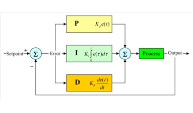
- P: proportional term. This term results in an output signal that is proportional to the process error (difference between desired parameter value—setpoint—and actual)
- I: integral term. This term results in an output signal that is the integral (i.e. sum over time) of the process error.
- D: derivative term. This term results in an output signal that is the derivative of the process error.
Other configurations are possible as well. For example, derivative term may act only on the feedback (output) signal, not the error signal, with proportional term in parallel with integral term.
In motion control application process error, described above, is difference between desired and actual motor positions, i.e. position error.
Effect of the PID Terms
Let’s take a look at a practical tuning exercise and take a closer look at the real effect of the various gains. Digital servo drive and motor with encoder feedback will be used to illustrate the effects of the various gains, as well as to provide some practical guidelines.
One of the best ways to evaluate PID tuning, is to look at the step response of a system.
In order to make sure that the system does not saturate and to avoid strong nonlinearities, small signal excitation and its response will be used. In addition to looking at the position response, torque will also be observed, as a measure of “how hard we are driving”.
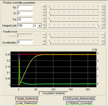
Below is a picture of the response with just a small proportional gain value. The integral and derivative gains are set to zero:
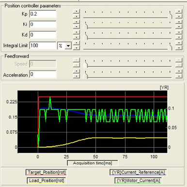
The red curve is the step reference. The yellow line is position feedback. The blue and green curves are reference and actual current respectively (which are proportional to torque).
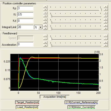
As seen above, the response is very sluggish. After increasing the proportional gain a few times, we can get to the following result:
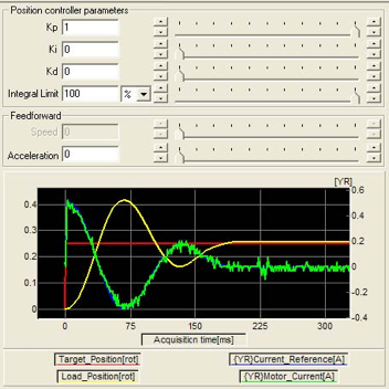
This system has almost no friction and exhibits large overshoot, even with small gains.
If friction is added to the system, damping characteristics will improve, but larger gains will be required. Addition of the friction will introduce small steady state error, not allowing the system to reach final target position.
This should always be the first step in servo loop tuning. Start with just proportional gain and look at the response.
If the system has a tendency to overshoot quickly, even with small gain, likely the friction is low.
If more gain is required to get any response, and the response is slow, the system has considerable friction. This determines the next step.
Low Friction System – Effect of Derivative Term
In a low friction system, the response has a tendency to become unstable quickly, even with low gains.
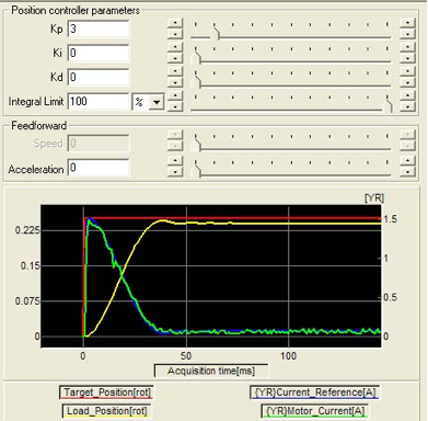
To remedy this instability, derivative action is required. Because the D term differentiates the position error which changes fast in case of instability it helps suppress the large changes by creating an opposing torque. In the system above, with the same proportional gain and with some derivative gain following response is obtained.
Large overshoot now is is eliminated. However, the overall response is also slower (meaning the time required to reach the target).
Frictional System – Effect of Integral Term
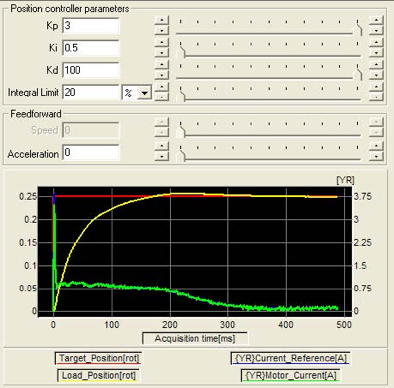
As noted above, by just using a proportional term, a stable response can be obtained, however the final target is not reached.
With added integral term, the longer the error exists, the larger the integral will become, resulting in a correction torque. In the system above, with the same proportional gain, and with added integral gain, position error (steady state error) is reduced to zero, even in the presence of friction.
Integral limit (also called anti-windup) should be used with an integral term, to avoid the integral term from becoming too large and taking too long to converge down.
PID Combined
One can notice that in case of the P and D terms in a low friction system that the steady state error is nonzero. Also in case of the P and I terms in a frictional system, some overshoot is introduced. In all these cases we can add integral and derivative terms respectively. For example, after adding some derivative gain to the frictional system one obtains the following response:
Tuning Tradeoffs
So far we have looked at the effect of each term on the response curve, in order to show how they contribute. From the response curves one can clearly see that in addition to the shape of the response, the response time is dramatically affected. Response curves have a few attributes that help quantify the response:
- Overshoot: by how much is the target position exceeded.
- Step response time: after how much time is 67% of the final target reached.
- Settling time: after how much time is the position settled within some % of the target.
- Saturation: one can run into current, torque or voltage limitation, which creates a strong nonlinearity typically resulting in overshoot and instability.
- Resonance: as the system gets excited at higher frequencies and power, system resonance may affect system response in unpredictable ways.
- Jitter: higher gains will cause small changes in the feedback to cause large jumps in currents. This leads to jitter (small oscillations at standstill).
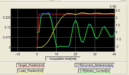
The current limit in our system is reached at 4A. Reaching this limit causes saturation and an ensuing oscillation (which does die out after coming out of saturation).
This means that motor and drive sizing should not only be based on the torque and speed requirements, but also on the required system response.
Mechanical transmission components should also be carefully selected to avoid system resonance (see previous article on the effect of coupling stiffness).
Lastly the feedback resolution should not just be based on positioning resolution requirements but also on desired system response.
Conclusion
Servo loop tuning is not a trivial task. Hands on experience is invaluable and above information will, hopefully, allow to achieve the desired response.
Although the behavior of the PID algorithm is well understood, there are many implementation details and system parameters that influence the response.
By utilizing a systematic approach of increasing the proper gains gradually while monitoring the response, stable behavior can be more quickly obtained.
In parallel, one should also observe current and torque to determine how much power is applied, or to avoid saturation. If the system is marginally sized, it may be necessary to adjust performance expectations.
This article was contributed by IntelLiDrives. Send email about this article to [email protected].
Subscribe to our FREE magazine, FREE email newsletters or both!
Latest News


