

Latest News
May 1, 2012
By Vince Adams
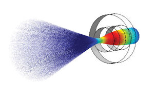 |
| Figure 1: This model uses the new charged particle tracing user interface to compute the trajectories of electrons in a spatially varying magnetic field. |
It is our mission to stay ahead of the curve,” says Bjorn Sjodin, vice president of product management for COMSOL Inc., Burlington, MA. Its multiphysics application, COMSOL, reflects this mission—and the functionality provided with Version 4.2a is no exception.
COMSOL Version 4.2a was released in October 2011. Two highlights of this release, the Particle Tracing Module and the LiveLink for CREO Parametric, the new modeling environment from Waltham, MA-based PTC, expand the impact of multiphysics simulation and its accessibility. Features like Image Import and Digital Elevation Map import are also enhancements, while many user interface improvements show COMSOL is listening and responding to customer needs. (See Figure 1.)
Particle Tracing Module
While particle tracing and streamline mapping have been available as computational-fluid dynamics (CFD) post-processing tools in COMSOL, the developers have expanded its reach by introducing new solver and visualization methods with the new Particle Tracing Module. As implemented, this is a secondary or bi-directional calculation on top of field and vector data that can compute particle position in a fluid mixing scenario or ion trajectories in an electromagnetic field.
Per Sjodin, the most important aspect of this module is flexibility. Essentially, COMSOL can plot the path of particles, either with mass or massless, under the influence of any number of forces and effects. Fluid forces and electromagnetic forces are the most common applications. However, the potential is theoretically limitless. (See Figure 2.)
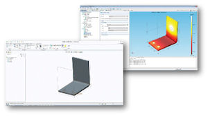 |
| Figure 2: The new LiveLink for Creo Parametric. |
COMSOL LiveLink Upgrades
LiveLink, the bi-directional CAD interface provided by COMSOL, supported SolidWorks, AutoCAD, Autodesk Inventor, Pro/ENGINEER and SpaceClaim in the previous release. This has been extended to support the newest modeling environment from PTC, Creo Parametric.
Another upgrade for LiveLink customers is the inclusion of a Parasolids-based geometry engine at no extra cost. Because the purpose of LiveLink is to provide native CAD support with persistent boundary conditions and properties, one might ask what value there is in a COMSOL-specific solid modeling tool. Sjodin says many geometric features or updates are solely to facilitate simulation.
“Consider a box that defines the flow or field domain around a part of interest. This box has no value in the design world, but is critical to the flow or electromagnetic solution,” he says.
The integrated Parasolids engine allows users to maintain the integrity of the native CAD part while leveraging geometry-based meshing and model setup. (See Figure 3.)
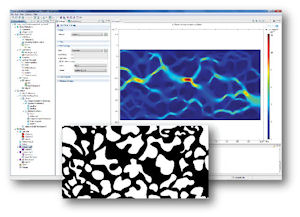 |
| Figure 3: A flow simulation using image-to-material conversion, where the equivalent flow resistance is computed for a porous structure. |
Image-to-Material Conversion
Isotropic. Homogenous. Uniform. All are common assumptions used to simplify the definition of a material for simulation. COMSOL customers have clearly communicated to the developers that each of these assumptions must be questioned if they are to expand the boundaries of advanced material engineering. Non-homogenous or porous material is particularly problematic when local effects must be considered.
Historically, an engineer would use CAD to manually trace around particles or voids in an image to create a finite element mesh (FEM) that was representative of local discontinuities. When you consider the porous media illustrated in Figure 3, where the black areas are open to flow and the wide regions represent obstructions, repetitive tracing—even with edge detection tools available in image-editing software—would still make creating a mesh tedious.
COMSOL Version 4.2a now offers a much more efficient means where a mesh is created over the image itself, using the pixel content to determine mesh density and property distribution. The user has additional mesh control tools if needed. COMSOL can utilize binary (black-and-white), grayscale and color images. Users can define thresholds based on the image color so clean edges aren’t required.
In addition to non-homogeneous materials, many electronics manufacturers requested and are using this tool for structural, thermal and electromagnetic analysis of printed circuit boards (PCB). With trace density increasing yearly, this image processing-based mesher has reduced simulation setup time significantly. (See Figure 4.)
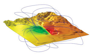 |
| Figure 4: An imported DEM was used to represent the underlying geometry for magnetic prospecting. |
A fourth notable enhancement to COMSOL Version 4.2a is the ability to import and mesh digital elevation maps (DEMs). These standard 3D data formats were developed to represent geographic or terrain features in the mining, oil and gas, and other civil engineering-related fields. COMSOL has been adapted to these applications, which fall outside the domain of traditional FE solvers.
User Experience Improvements
In post-processing, COMSOL has added dynamic section and iso-surface control at the request of customers. This is a commonly used visualization tool in FE analysis, and a long-awaited addition.
COMSOL supports cluster computing with a simple licensing structure, which allows multi-node computing with a floating license and multi-core computing with a node-locked license. Large parametric sweep studies are ideally suited to leverage cluster computing but can create enormous amounts of data that must eventually be mined for trend plots. In Version 4.2a, COMSOL allows users to run these resource intensive studies but then save only the user-defined output required to generate these plots.
Joined datasets have been added to COMSOL Version 4.2a to allow cross-study data comparison. Users are now allowed to compare results across similar datasets at different points in the time history—and even with dissimilar meshes. Output variations from boundary condition, flow media properties and even mesh density can be readily evaluated for greater insight to the problem at hand.
Looking ahead, COMSOL Version 4.3 is set for release this month. Users can look forward to enhancements to the nonlinear structural solver, which will provide more material models. Version 4.3 will also feature two new modules for corrosion and pipe flow.
Vince Adams, an account manager for LMS, is a simulation educator, consultant and speaker. He has authored three books on finite element analysis and many magazine articles. Contact him via [email protected].
MORE INFO
COMSOL
Subscribe to our FREE magazine, FREE email newsletters or both!
Latest News
About the Author
DE’s editors contribute news and new product announcements to Digital Engineering.
Press releases may be sent to them via [email protected].


