SolidWorks 2010: Faster & Smarter
In this latest release of the workhorse design solution, productivity and sustainability take center stage over an array of dazzling new tools.


Latest News
January 3, 2010
By Kenneth Wong
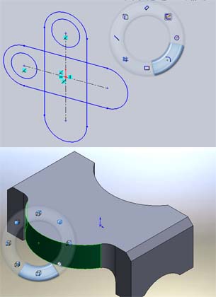 In SolidWorks 2010, you can use mouse gestures to activate the multiple-choice wheel. In sketch mode, the wheel gives you quick access to commonly used sketching tools; in 3D mode, the wheel lets you switch from one perspective to another without having to rotate the model manually. |
It’s difficult to single out certain features of SolidWorks 2010 as revolutionary steps. As the company has stated, this release focuses on productivity (a “faster, smarter, rock solid” release, according to the launch site) instead of dazzling new tools. And, since most Desktop Engineering readers are familiar with how leading midrange CAD programs work—offering 2D sketching, 3D modeling, and dimensioning functions—this article is devoted to exploring some of the new tools debuting in 2010 release of this respected solution.
Interface Improvement
One of the most notable enhancements to the SolidWorks interface is the introduction of gesture-based sketching and modeling. To activate this feature, you need to go to Tools > Customize > Mouse Gestures, then select either 4 or 8 gestures. With gestures turned on in sketch mode, you can simply right-click and drag your mouse down (as though you were drawing a straight line from top to bottom) to launch the multiple-choice wheel. Depending on whether you’ve selected 4 or 8 gestures, the wheel gives you a series of sketching options: for example, the ability to directly select a circle or square, then dimension it.
In 3D mode, when you right-click and drag your cursor down, you launch a multiple-choice wheel that presents you with a series of perspectives. You can then easily move from front to back plane, or return to orthographic views, making it easier to pick certain hard-to-reach surfaces without rotating the model.
Placing the cursor directly on the wheel will automatically select the nearest feature, be it a square or a circle. Long-time SolidWorks users accustomed to selecting the desired sketch or modeling features from the ribbon bar menu might need to invest some time and effort in the new approach. But you can become more productive, as the gesture wheel places some of the most commonly used commands at the tips of your fingers (or mouse cursor).
Focus onSustainability
Sustainability Xpress, a new plug-in that ships with every copy of SolidWorks 2010, was developed in conjunction with PE International, a sustainability consultant and solutions provider. Using a series of simple input parameters and dropdown windows, the tool lets you predict the environmental consequences of your manufacturing decisions with regard to choice of material, manufacturing method, production site, and sales location.
Based on your CAD part’s 3D geometry, the software can deduce how much material is required to produce the part. Using some known facts about material properties, manufacturing practices, and transportation procedures, the software estimates your parts’ environmental impacts, revealed as air pollution, water pollution, carbon emission, and energy consumption.
For example, a part that’s meant to be used in North America but produced in Asia increases energy use because of the fuel required to transport the part from its production site to deployment site. By contrast, choosing plastic instead of steel might decrease carbon emissions because of the energy-intense process of making steel.
The software doesn’t give you preset targets, such as a specific volume of energy consumption or a recommended level of carbon emission. Instead, it lets you use a manufacturing scenario—say, producing a 0.16-lb. sheet-metal part in Asia, to be sold in the U.S.—as your baseline. Subsequent scenarios using a different material, production method, or manufacturing site are judged against the baseline.
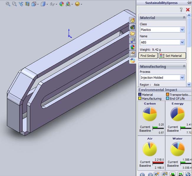 Sustainability Xpress, debuting in SolidWorks 2010, uses a series of simple input parameters and dropdown windows that let you predict environmental impacts. |
Even if you’re unconcerned about environmental impacts, you will find the software’s Find Similar feature a handy tool. It enables you to identify alternative materials with similar, greater, or lower tensile strength, thermal properties, mass densities, and shear values.
Sustainability Xpress currently works only on parts, not assemblies. It’s also available to SolidWorks 2009 users as a free download from SolidWorks Labs. If you install it in SolidWorks 2009, you’ll find the application under the Tools menu. In 2010, Sustainability Xpress lives under the Evaluate tab, alongside your analysis tools.
Goal-Driven Parameters
In SolidWorks 2010, after running Simulation Xpress (the FEA analysis wizard), you’ll be asked if you wish to optimize the design. If you choose “Yes,” you’ll find yourself in the Design Study environment. (You may also initiate a Design Study session by clicking on its tab under the Evaluate tab, but you’ll probably need simulation data to use as input parameters.)
In the Design Study environment, you can select some of your part’s parameters—such as an extrusion height and a bend angle—as Variables. Then you can pick certain constraints: for example, a Factor of Safety greater than 1 (determined by the previous simulation data). Next, you set a goal, such as reduction of mass or surface area. Then run the session, allowing the software to regenerate the part by incrementally altering your part’s variable dimensions.
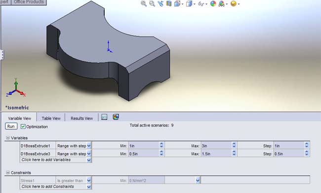 The Design Study feature in SolidWorks 2010 lets you automatically generate various configurations of your part, with certain goals in mind. Afterward, you may pick the option configuration recommended by the software. |
From all possible permutations, the software presents one as optimal. If you agree with the recommended option, you can apply the edits. This could be valuable if you know the maximum load or deformation your part is meant to endure and you wish to find the best geometry. You can experiment with your part manually, one parameter at a time, or run a Design Study to let SolidWorks identify the best configuration
Multi-body Parts
In SolidWorks 2009, the software introduced a feature called Convert to Sheet Metal that automatically transformed a solid part into a sheet metal part. In 2010, you have the option to create multibody sheet metal parts.
When adding a new sheet metal feature, a crucial checkmark under the Sheet Metal Property Manager window lets you specify whether you want the new feature (for instance, a boss flange) to merge with the existing part. If you uncheck the Merge Results option, you get a sheet metal part with two separate bodies. Similarly, in part creation, you also have the option to merge a subsequent extrusion or sweep with the existing geometry. If unchecked, the outcome creates a multibody part. These multibody sheet metal and solid parts let you treat each body separately (as you would your assembly components). You could, for example, unfold a portion of the sheet metal part as a separate flat pattern or conduct stress analysis on a single body. Bear in mind, however, that some of the tools under Evaluation Tab (Simulation Xpress and Sustainability Xpress, to name but two) don’t support multibody parts.
Event-Based Motion Study
In 2010, SolidWorks introduces Event-Based Motion simulation (requires SolidWorks Simulation Professional). With this feature, you can define your assembly components’ contacts and behaviors as Triggers, which set in motion another event, to be completed within a certain time. Industrial machine designers stand to benefit from this tool tremendously; they might use it to refine and adjust the cycle time of each machine operation to improve efficiency.
Decals and Depth of Field
In PhotoWorks, the rendering plug-in that comes with SolidWorks, you have the option to project 2D images on your 3D models, a handy tool for consumer goods designers who need to figure out the right logo placement or detailing in fabrication. In 2010, you can toggle previously applied decals on and off, allowing you to view the superimposed 2D images within SolidWorks environment, before entering PhotoWorks’ rendering environment.
Another feature of PhotoWorks that adds realism to the rendered images is simulated depth of field, which lets you deliberately blur background objects in your rendering. In 2010, you have the option to adjust the depth of field by controlling the blur rate. (Note: To access the Depth of Field dialog box, you need to be in a camera view.)
As always, SolidWorks remains a stellar midrange CAD program, complete with basic stress analysis (Simulation Xpress), data management (PDMWorks), and rendering (PhotoWorks). By introducing Sustainability Xpress in 2010, SolidWorks paves the way for other CAD vendors to consider adding green manufacturing tools. Its simplicity and ease of use make the feature easily understandable. The Design study and event-based simulation also set it apart from its rivals, but both tools require time and patience to master.
More Info:
SolidWorks
SolidWorks Premium
>Price: $7,995
SolidWorks Professional
>Price: $5,495
SolidWorks Standard
>Price: $3,995
Video demonstrations of many of the features discussed above can be found at DE’s Virtual Desktop blog.
A Look at SolidWorks Sustainability Xpress
A Look at Multibody Sheet Metal in SolidWorks 2010
Design Study in SolidWorks 2010
A Look at PhotoWorks 2010’s Decal and Depth of Field Simulations
Kenneth Wong writes about technology, its innovative use, and its implications. One of DE’s MCAD/PLM experts, he has written for numerous technology magazines and is the author of DE’s Virtual Desktop blog at deskeng.com/virtual_desktop/. You can follow him on Twitter at KennethwongSF, or send e-mail to [email protected].
Subscribe to our FREE magazine, FREE email newsletters or both!
Latest News
About the Author
Kenneth Wong is Digital Engineering’s resident blogger and senior editor. Email him at [email protected] or share your thoughts on this article at digitaleng.news/facebook.
Follow DE

