Solve Key Problems in Composite Simulation
Whether you are looking at pre-processing, post-processing or material testing, composites are orders of magnitude more complex than traditional materials such as metal and plastic.


Latest News
August 1, 2013
Like a very tricky sandwich, composite materials are usually laminated structures, made up of layers (plies) of material, stacked one on top of the other. These layers often have fibers running through them, and the angle of those fibers can vary from layer to layer (0 °, 45 °, 90 °, etc.). There can be dozens, or even hundreds of layers. There might be more layers in some areas, and fewer in others so the overall width of the structure varies from area to area. The final properties can be hard to predict.
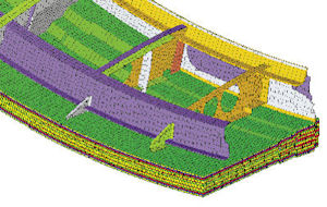
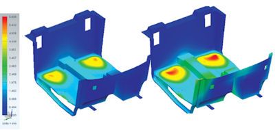
 Analysis of composite compressed natural gas tank doors on a transit bus. Images courtesy of Composites Innovation Centre. |
“If you don’t have a balanced, symmetric laminate, your part can twist when you apply a tensile load,” says Alastair Komus of Composites Innovation Centre. “You can take advantage of that in some parts; other times you want to avoid it entirely. But it’s a complication that your software needs to be able to predict.”
On a curved part, the effective angle of the fibers can change from place to place. That orientation is a huge factor in analysis, according to Komus: “Siemens NX allows you to define a starting point on your part and, as you drape your material over a curved surface, the program tells you how the alignment of those fibers changes.”
Taking a Look
Just being able to see what’s going on in a composite structure can be a big challenge, notes Altair Senior Director Robert Yancey, Ph.D.: “Composites add one or two more orders of magnitude to the information you have to be aware of when you analyze a structure.”
The same issue persists on the post-processing side, he says.
“Damage usually initiates at a single layer, and you want to be able to quickly home in on where that damage is occurring,” Yancey explains. “With Altair, you can color-code the layers. But if each layer has a different fiber orientation and you want to visualize the fiber orientation of a particular layer, you’ve got to select that layer ]and look at it separately]. It works fine, but it’s not a very intuitive process right now. I believe there will be more efficient ways of integrating that data.”
 Altair’s HyperWorks includes many features to help model and analyze complex composites parts, including 3D representation of plies. |
 Seat pull analysis for the front tub of the Kestrel concept vehicle. |
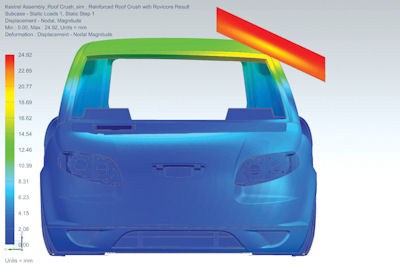 Roof crush analysis of the Kestrel concept vehicle. |
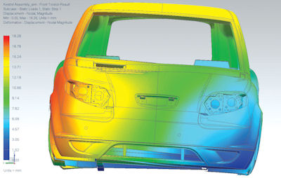 Torsion analysis of the Kestrel concept vehicle. |
Optimization Offers Advantage
Yancey points to Altair’s optimization technology as being able to guide users with respect to the general structure of the laminate.
“We can tell the designer which angle ply should be where, what angle ply should dominate where in the structure, where you can get away with dropping off some plies, or where you might need to build up some plies in order,” he says. “We’ve been able to demonstrate to many of our customers that you can develop a composite laminate design that can save 15% to 30% of weight over a traditional composite design.”
In addition to saving weight and saving materials, think about the complexity of the composite itself, advises Altair Business Development Manager Giuseppe Resta.
“You may have hundreds of plies of different orientations and different thicknesses. The question is, where do you start? There are so many solutions that, in theory, give you a satisfactory design, but where does the engineer go to get the best out of it?” Resta continues. “Optimization guides you to what may not be an intuitive design. Optimization is not just an add-on to improve something that you’ve already done; it can be a design strategy that you adopt at the beginning to gain insight into how to use this expensive material at its best.”
Errors in your Model
“What makes design space exploration possible is a tool that’s reliably accurate over the entire design space,” observes Scott Leemans, principal engineer at Advatech Pacific. “You have to quantify the uncertainties over the entire design space to ensure that is true.”
 Altair’s set of simulation tools for composites analysis is integrated into HyperWorks’ optimization framework. Here, an IndyCar chassis from Dallara is shown. |
In general, he says, for complex systems such as aircraft, the traditional finite element analysis (FEA) approach leads to models that are tuned to match tests as the project progresses.
“In other words,” says Leemans, “the individual errors are not identified and then quantified over any significant portion of the design space. I do not believe that error quantification is adequately addressed—or even adequately facilitated by most packages. It is left to the user to decide when and how they ensure the accuracy of their models.
“We calibrate, verify, and validate all of the analysis models that go into our tools with testing,” he adds. “We use a test matrix that covers the same design space over which the tools are valid.”
Material Property Problems
There’s another problem lurking at the very heart of composite simulation: garbage in, garbage out.
| Basis Values Basics A-basis and B-basis values (sometimes called allowable values) are statistically computed confidence bounds on estimates of a material property, usually strength. Composite material properties can vary, which makes definitions of material properties somewhat fuzzy. That’s where basis values come in. For example, we can say with 95% confidence that 99% of the material will meet or exceed the A-basis value, and 90% of the material will meet or exceed the less-conservative B-basis value. Or can we? Material property basis values can be computed from tests using three batches of material, all from the same manufacturer. It’s like throwing three darts at a wall, then drawing two concentric circles around them. The circles are your acceptance region (inner) and basis values (outer). When subsequent manufacturers step up and throw, their darts must hit the inner circle or risk their materials being rejected. Within the acceptance region, we cannot tell any significant difference among the samples; if your sample lands in that region, it’s considered identical and accepted. But that circle is small and hard to hit. In fact, these computed acceptance criteria are frequently unrealistic for many composite part manufacturers (CPMs). These unrealistic expectations have significant repercussions for the industry. You might think the problem stems from the small sample size (three batches) initially used to compute the basis values. But, because of the way basis values are computed, adding more samples makes matters worse. With more samples, we become better at telling differences among batches. Thus, our acceptance region shrinks. This could, theoretically, result in many, most or even all material samples being rejected. Generic Basis Values With generic basis values, the acceptance region is defined first, from a much larger set of samples from multiple manufacturers, such that at least 90% of CPMs will produce acceptable product by following documented procedures. Basis values are then computed for this acceptance region. This gives us a much larger acceptance region, and lower basis values, than traditional methods. But, and this is key, it gives us basis values that CPMs can actually meet. In fact, we can conclude with 95% confidence that their materials will support the generic basis values. This is a stronger claim than that which is currently used to certify materials, and can result in unequivocal certification of composite parts for the majority of CPMs using a material’s generic basis values. —Elizabeth Clarkson, Ph.D. and Mark Clarkson |
“In CAE, you need a proper input to get a proper output,” says Altair’s Resta. “We need to have a mature material on which to apply CAE design. Material knowledge is the basis of composite design.”
You can’t get good results without good material data—and unfortunately, when it comes to modern composites, good material data is sorely lacking. The reasons are manifold. Just as analyzing composites is orders of magnitude more complex than analyzing traditional materials, testing composite materials is orders of magnitude more difficult, and produces correspondingly more data. (Editor’s Note, see “A composite Sketch of ACMs” for more information.)
In the aerospace industry, says Yancey, “every laminate configuration you’re going to use has to be tested. If you’ve been using a six-ply laminate and you want to change to a 10-ply laminate, you’ve got to repeat all those tests.” That’s thousands of tests. This makes composite materials extraordinarily expensive to test. Projects like the Boeing 787 or F-35 Joint Strike Fighter accrue tens of millions of dollars in composite materials testing expenses alone.
“Because of the expense of testing those materials,” says Yancey, “and the fact that composite usage is relatively new in many industries, a lot of that material data is considered proprietary.” For example, Boeing isn’t anxious to spend $100 million qualifying a material and process, and then give that information to Airbus (and the rest of the industry) for free.
This also means changes can be almost prohibitively expensive to contemplate, even when a potentially superior material appears.
Simulation to the Rescue Eventually
“We see CAE as a way to limit the actual material testing necessary,” says Resta. “You’re going to use the physical testing for the extreme cases and then, once you have confidence in CAE, you can extrapolate to the other, less-severe conditions. That’s what’s going to be required for companies to switch to new material systems as improvements are made.”
There is an active community working on virtual simulation of materials for qualification, but it’s a new idea. “It will take some time to get better accepted in the industry,” says Yancey.
It’s not a Composite until it’s a Part
“Aluminum is aluminum before you turn it into a part,” says Advatech’s Leemans. “Composites aren’t. It’s not a composite until it’s been built.”
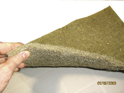 Non-woven biofiber mat is used as composite reinforcement. |
Composites are very, very process-dependent, and variations in the manufacturing process can have profound effects on the final long-term behavior of a part. Change suppliers or build on a hotter day, cure a part a bit longer, and you can wind up with surprisingly large differences in material properties. “We in the industry don’t do a good job of modeling the idiosyncrasies, part by part, ]arising from] the manufacturing processes,” says Leemans.
Those idiosyncrasies include wavy or missing fibers, porosity and voids, and spring-back—the tendency of a composite part to change shape when removed from the mold.
“I worked on one part that was a simple front panel,” recalls AlphaSTAR senior scientist Jonas Surdenas. “But the edges were a different laminate than the center and it bowed. When you heated it up, the bow disappeared. It’s a mismatch between the coefficient of thermal expansion and the modulus. If there’s enough interplay between the different parts, it can cause deformation or residual thermal stresses in there.”
Some of these things are immediate problems: Spring-back might mean the two halves of your engine nacelle don’t mate, for example. On the other hand, porosity might not be a problem for months or years, but it will ultimately shorten the part’s life.
“The effect of these defects is a major concern,” says AlphaSTAR Founder Frank Abdi, Ph.D., noting that FEA “cannot account for all these things.”
Computer simulations generally assume a perfect build; it’s hard to anticipate random voids and plug them into the model.
“Engineers use reduction factors and things like that,” says Abdi, knocking down the computed strength of composites to account for manufacturing defects. “That causes overweight parts.”
The Complexities of Failure
Composite materials don’t fail the way that metallic materials do, and different types of composites fail differently.
“When we’re using NX,” says of Composites Innovation Centre’s Komus, “there are about six different failure theories you can select from. Some are good for directional materials; others are good for woven materials. Some are better for some load cases than for others. You definitely have to be very careful in terms of what failure criteria you use.”
Composite structure of the Kestrel concept vehicle, supported by a metallic chassis.
Advatech’s Leemans observes that designers could perhaps get a little closer to the edge than they currently do if they had better tools. For now, though, they can’t predict exactly how a failure will initiate.
“The failure modes jump around,” he adds. “How do you capture that? Is it matrix failure or a fiber failure? Is it both? Is it an interface between the two? The heterogeneity of the problem at multiple scales really adds complexity. A few companies out there—like Firehole Composites ]now part of Autodesk], AlphaSTAR—are working on progressive failure analysis, trying to figure out when cracks initiate, when the matrix starts to break down and degrade, how the de-lamination progresses.”
“There’s still a pretty big disconnect between the as-designed and as-manufactured composite structures,” says Altair’s Yancey. “Advances are being made in manufacturing simulation of composites, but there’s a lot of room for new capabilities and innovation for better understanding the manufacturing process.”
| Q&A with Peter Foss, Staff Researcher at General Motors Q: What Kind Of Composites Do You Work With? A: I tend toward the short-fiber injection-molded plastics side of things. You’ll find ]fiber-filled plastics] in powertrain applications such as oil pans and intake manifolds, and on the vehicle side in bracketry and transmission and engine mounts. People are looking to save mass and using reinforced plastics is one way to do it. The issues that we fight with composites in the auto industry is that our development cycles are so fast that, if we can’t predict it accurately, it’s a really serious drawback to implementation of new materials. Q: Are You Using Simulation to Predict Part Properties? A: Our ability to analyze plastics and composites and to account for manufacturing processes and effects is very far behind where we are with steel, especially, and with metals in general. Plastic composites are almost universally treated as an isotropic material, so you’ve lost all the effects of processing and fiber orientation. Q: But They Aren’t Isotropic? A: Q: How Are The Fibers Oriented? A: The fibers are oriented by the flow of the material into the mold. It’s mostly controlled by where you put the gate. If I gate a part in two locations, I have two parts. They’re different. Their structural response is different. The different flow simulations predict that, or at least try. Q: How Does This Feed Into Structural Analysis? A: People use mold flow analysis all around the plastics industry, and people do structural analysis, but it’s different people with different goals asking different questions. With tools like Digimat from e-Xstream Engineering, we can bridge the gap between those analyses and start to understand what’s going on with these materials. Q: What is Digimat? A: That’s why the ‘pick a number’ isotropic analysis method isn’t very robust. You end up over-designing. Since you’re not accounting for orientation and local effects, you have to make it so the weakest direction is still ]sufficiently strong.] —Mark Clarkson |
Contributing Editor Mark Clarkson is DE’s expert in visualization, computer animation, and graphics. His newest book is Photoshop Elements by Example. Visit him on the web at MarkClarkson.com or send e-mail about this article to [email protected]. Elizabeth Clarkson is chief statistician for the National Institute for Aviation Research. Visit her site at BethClarkson.com.
More Info
Subscribe to our FREE magazine, FREE email newsletters or both!
Latest News
About the Author
Mark ClarksonContributing Editor Mark Clarkson is Digital Engineering’s expert in visualization, computer animation, and graphics. His newest book is Photoshop Elements by Example. Visit him on the web at MarkClarkson.com or send e-mail about this article to [email protected].
Follow DE

