

Latest News
February 2, 2009
By Fred C. Jensen
Page 1 | 2 »
Engineers all over the world are being challenged with the task of quite literally saving our planet. Today’s efforts revolve around energy production and how it affects global warming. As a result, complex mechanical assemblies are being developed and it becomes critical to simplify their fluid flow analyses with regard to handling resultant pressure drops in a practical flow path. Here are two examples.
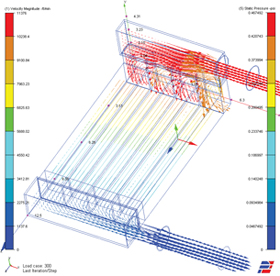 These are static pressure vectors flowing through a compact heat exchanger manifold. | 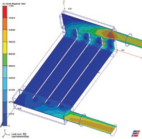 This is a velocity profile of the compact heatexchanger manifold assembly. |
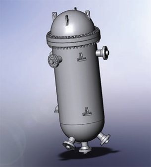 This MCAD model of a nuclear reactor illustrates just one primary coolant loopfor clarity. |
The first example is a fluid-to-fluid heat exchanger (HE) that was designed to raise the efficiency of energy conversion in fuel cell systems by exchanging heat from hot exit gases with the cold inlet gases. This innovative heat exchanger, known as the HEP (heat exchange platform), was designed and built by engineers at Catacel Corp. in Ohio. The core of this heat exchanger has thousands of very small flow channels made out of 0.003-in. thick metal foil. This design enables the exchange of approximately 90 to 140 watts of energy per 1.0 cubic in. of heat exchange core at an operating temperature of 800 degrees C. These are impressive numbers and to do this at temperatures and flow rates useful to fuel cells is a breakthrough technology. The repetitive small cross-sections of long thin passages present an analytical challenge to the fluid dynamist. Our question is how does one calculate the fluid resistance that this HE offers when it is placed in a manifold design of a portable power unit?
The second example is another HE at the opposite end of the size spectrum. It is a nuclear reactor weighing 132 tons for just the primary steel vessel. The reactor interior contains approximately 30,000 fuel rods held together by multiple tube sheets with the coolant fluid flowing back and forth over the rods. Here the problem becomes complex again due to the repetitive maze of rods in the flow path. As before, our question is, how does one calculate the effect of the fluid resistance when this vessel is placed in the primary coolant loop of a stationary power unit?
When faced with a complex technical problem, break the problem down into small solvable pieces and write down the steps. If one does that to these two examples described above, one recognizes that they are the same types of problem.
 |
The suggested solution steps for both of these flow-pressure drop problems are as follows:
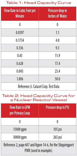
1.) First, review the historical technical data. Find out how this problem was solved in the past. This can be through corporate records of past jobs or through a literature study of past similar efforts. In our two examples, actual test data was available from previous work.
2.) Write down all the known input parameters and an estimated result. Include an estimated cost to complete. Does the estimated result produce the desired goals?
3.) Construct a CAD model of the hardware.
4.) Use the actual CAD model to construct the computational fluid dynamic (CFD) model.
5.) Null out the complexity of the CAD model by suppressing all of the metallic components. In a CFD flow-pressure drop model, one needs only to analyze the fluid space inside the components and not the components themselves. Therefore, the CAD model can be used with all the fabrication complexity that is required to build it. We null out the unneeded components by setting the element count to zero for each respective metallic component. Each fluid space will have an element count either generated automatically by the CFD program or specified manually by the analyst.
6.) Finally, here is the key step in this sequence. The goal is to analyze the flow patterns and pressure drops in the manifold in the first example, and the primary coolant loop in the second example. Each of these loops has a series of pressure drops. Do not model the fluid spaces for the complex mechanical component. Instead, substitute a mathematical expression for the flow-pressure characteristics for that complex mechanical component. (see Reference 1.)
Page 1 | 2 »
Subscribe to our FREE magazine, FREE email newsletters or both!
Latest News
About the Author
DE’s editors contribute news and new product announcements to Digital Engineering.
Press releases may be sent to them via [email protected].


