

October 18, 2011
Caltech researchers use Abaqus FEA to design self-deploying composites booms for satellites.
Manmade satellites have to fit a lot into a compact package. Briefly protected inside a rocket while blasted through the atmosphere, a satellite is launched into Earth’s orbit, or beyond, to continue its unmanned mission alone. It uses gyroscopes, altitude thrusters and magnets to regulate sun exposure and stay pointed in the right direction. Once stable, the satellite depends on solar panels to recharge its internal batteries, mirrors and lenses for data capture, and antennas for communications with the folks back home.
Whether it’s a bread-loaf-sized nano, or the school bus-proportioned Hubble Telescope, every satellite is susceptible to static electricity buildup from solar wind, the freeze of the Earth’s shadow (or deep space), and tiny asteroids that pepper the route like killer bees. In such a hazardous environment, the functional longevity of the average satellite is limited.
Figure 1. A MARSIS satellite nears Mars, showing one composite antenna boom already deployed and a second boom in the process of unfolding. (Image: European Space Agency)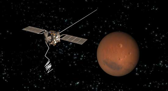
While more than 2,000 satellites are estimated to be in Earth’s orbit at any one time, the countries and private enterprises that own them must keep sending up replacements at a pretty steep price tag. As a result, aerospace engineers continually strive to come up with smaller, lighter satellites that are cheaper to make, less expensive as rocket payloads and still capable of fulfilling their high-tech job descriptions.
Satellite Hardware Solutions
The size of critical hardware like solar sails, solar concentrators and reflector antennas is limited to some degree by the weight and stowage capacity of each satellite. But to function properly, much of this hardware needs to expand outside the confines of the spacecraft that carries it. The engineering solution? Design deployable structures that unfold once the satellite is in position. This way, a big piece of hardware can be compacted into a small configuration for transportation, then expanded to operational size in space.
Many satellites accomplish this important task using motors and gears for mechanical deployment of their hardware, but other designs rely on self-deployment instead, using energy stored within the hardware itself during compaction. Imagine folding a plastic drinking straw repeatedly into a small, zigzagged cluster, then letting go so it springs back into a straight line. This kind of release action happens without the additional mass and power source that are required for mechanically deployed booms.
As seen in Figure 1, self-deployable booms, made from flexible composites, were used for the antennas on the European Space Agency’s Mars Express Spacecraft (MARSIS). They are currently being designed into a number of future satellite missions. The booms are lightweight, easily folded, less expensive “and fairly insensitive to friction, compared to traditional motorized designs.
Modeling Complex Behavior in Zero Gravity
Structures of this type have actually been proposed for decades, but their behavior “highly non-linear geometric deformation, buckling, dynamic snapping, etc. “was difficult to quantify and predict. As a result, earlier boom components were usually refined through repeated, costly physical experiments, including ones conducted during the 22 seconds of weightlessness generated in a plunging test aircraft (see Figure 2).
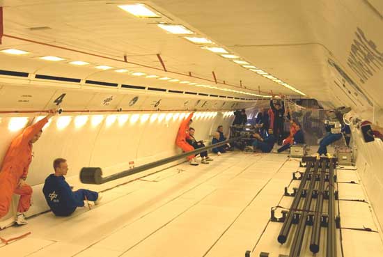
Figure 2. A deployable inflatable boom test was carried out in mid-air over the Atlantic Ocean in an Airbus A300 ZERO-G aircraft by a team from the Institute of Composite Structures and Adaptive Systems at the German Aerospace Center (DLR).
“But now, we can accurately portray these features using realistic simulation,” says Chinthaka Mallikarachchi, a postdoctoral scholar working with Professor Sergio Pellegrino at the Space Structures Laboratory of the California Institute of Technology (Caltech). “We can optimize the structural design of self-deployable booms through finite element simulations, and conduct physical tests only on our final designs. Since ground testing on Earth of structures that are going to be deployed in the zero-gravity vacuum of space is either difficult or very expensive, such virtual testing is the answer to a lot of the challenges we face.”
Mallikarachchi’s work over the past several years, on the simulation of a carbon-fiber-reinforced boom that can be folded around a spacecraft, was carried out almost exclusively using Abaqus Unified Finite Element Analysis (FEA) from SIMULIA, Dassault Systemes brand for realistic simulation.
“SIMULIA’s academic package has been quite helpful to us in conducting this kind of research,” he says. “We used the meshing and visualization features in Abaqus/CAE a lot. The Abaqus/Explicit solver is the most important feature for us, since it accurately captures all the complexities of our boom designs. And the general contact, shell general section, equation constraint and restart features were very user-friendly, as were the availability of python scripting and keywords for input files.”
The modeled boom is a 1-meter-long, thin-walled (0.22mm) tube that’s 38mm in diameter. It is made of two plies of plain-weave carbon fiber in an epoxy matrix. Certain regions of the tube were weakened by cutting away some of the composite material to form tape-spring hinges, so the tube could be folded around the satellite (labeled as “spacecraft” in Figure 3) without causing any damage. Three possible hinge designs, with different slot parameters, were considered. The FE mesh was made finer over the hinge regions to capture the details of the complex deformation occurring in these regions.
Figure 3. The boom design challenge: Fold it around a satellite, then release it and have it fully extend.
Overcoming Research Challenges
Early research used micromechanical modeling to capture the behavior of the boom’s thin laminate material through homogenization of a periodic unit cell (with Abaqus/Standard). From this, the material stiffness was computed in the form of a matrix and used to define the shell elements in the Abaqus/Explicit simulations of the quasi-static folding and dynamic deployment. The numerical simulations were then integrated with a material failure criterion. The combination of these tools (see Figure 4) allowed an analysis of the detailed effects of hinge design changes on three different boom models. This led to identifying the design that could be most safely folded and deployed.
Modeling the boom deployment involved first pinching the hinges to fold the boom around the spacecraft, then releasing all constraints so the boom dynamically deployed and self-latched.
“This behavior needed to be fully understood and optimized, since overshooting at the end of deployment could damage the boom, the spacecraft or other equipment attached to it,” says Mallikarachchi. “Alternatively, a too-slow, highly damped deployment might never achieve the fully expanded configuration that’s needed.”
Figure 4. A summary of several years of Caltech research, using Abaqus FEA, to develop a deployable composite boom for satellite hardware deployment.
Project Test Launch: Simulation vs. Reality
During the FEA simulations, the first boom design overshot the fully deployed configuration and was rejected. When the failure analysis and hinge angle were optimized against the time response (full deployment occurred in about 0.3 seconds), Design III performed better than Design II.
With their simulation data in hand, Mallikarachchi’s team then built and tested a boom according to Design III specs, filming the results from two different camera angles. Side-by-side motion comparisons of Abaqus FEA and boom deployment (see video below) confirmed that the real boom also deployed in 0.3 seconds, became fully latched, then oscillated around the deployed configuration in excellent agreement with the simulation.
Side-by-side images of the boom test and Abaqus FEA model demonstrate the accuracy of the simulation.
Find more videos like this on DE Exchange
“Our studies showed that the most critical points are the fully folded configuration and, during deployment, the point at which the second hinge latches, affecting the load on the root hinge,” says Mallikarachchi. “The hinge transition region between the straight and curved part of the slot experiences the most stress/strain, so special care should be given to this area during fabrication of this kind of boom.”
The Caltech team’s validation of their boom design paves the way for further exploration of satellite hardware deployment. “Our simulation techniques can be used to design deployable booms with multiple hinges and optimized boom geometry to meet any specific mission requirements,” says Mallikarachchi. “Future work could consider alternate laminates, and thermal and viscoelastic effects in different materials.”
INFO
Subscribe to our FREE magazine, FREE email newsletters or both!
About the Author
DE’s editors contribute news and new product announcements to Digital Engineering.
Press releases may be sent to them via [email protected].


