Structural FEA in the Automotive Industry
A look at some of the finite element analysis technologies involved in creating a vehicle--and the simulation methods involved.


Latest News
March 1, 2014
By Tony Abbey
Editor’s Note: Tony Abbey teaches live NAFEMS FEA classes in the US, Europe and Asia. He also teaches NAFEMS e-learning classes globally. Contact [email protected] for details.
The overarching objective of all automotive manufacturers is to move predictive simulation to the early design stage. The benefits of influencing design earlier, reducing the number of design cycles and eliminating much physical testing are well understood. Target project timescales from concept to prototype definition are very aggressive within the industry, with timescales of the order of 18 months being discussed. Considering the trend to extend the range of vehicles to give a broad product portfolio, this is an extraordinary achievement.
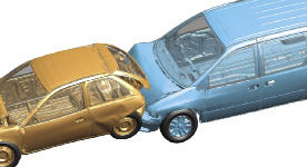 Last two vehicles in a multiple-vehicle crash simulation. Image courtesy of Arup/Oasys LS-DYNA. |
Vehicle crash analysis is probably the most well known simulation in automotive design, and indeed is seen as the role model for other disciplines within the industry. Here, the emphasis is now on prediction of vehicle response to validate design strategies and permit change well before available physical test articles. Most other simulation processes are also now being used earlier in the design loop. However, current simulation technology limitations imply a traditional forensic and redesign process in some areas. In such cases, advanced research and collaboration with academic institutions is the way forward.
Crash Simulation
The requirement for a crash simulation is regulated through specific accident scenarios and safety targets. The objective of vehicle crash design is to allow energy absorption to take place throughout the vehicle. Instead of designing a civilian armored vehicle, where all is swept before it, the vehicle is designed to progressively crumple at even modest impact levels.
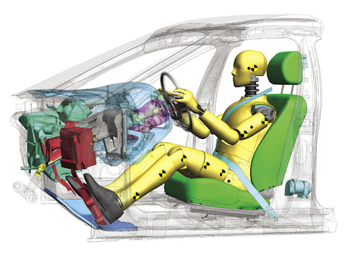 Crash dummy model. Image courtesy of Arup/Oasys LS-DYNA. |
Every component in the chain of events is designed to crumple, crush or in some way absorb energy. Modeling requires sufficient mesh fidelity and accurate material strain rate behavior to provide realistic responses, as components evolve in the overall design.
Finite element analysis (FEA) of vehicle crash uses explicit analysis (described in “Impact, Drop and Crash Testing and Analysis,” Desktop Engineering, August 2013). The size and complexity of crash models have now reached the stage where sophisticated pre- and post-processing is required. For example, an engineer must identify and visualize response of the hundreds of components in the vehicle assembly during impact—using transparency, section cutting, dissection, etc. Physical test result videos are overlaid on simulation animation for correlation. Graphical plots of force, displacement or acceleration against time are spawned interactively from key points to compare against test data.
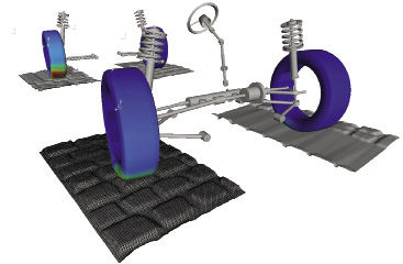 MotionSolve vehicle model. Image courtesy of Altair. |
Crash test dummy simulation is now a mature area within vehicle crash analysis. Specific models include gender, age and percentile range of height, weight, etc., and provide standardization and repeatability. Dummy-based prediction is a simplification of real-world response of occupants in a crash, of course, and there is research to move beyond this. But it’s a difficult and challenging area from many perspectives.
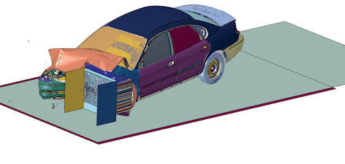 Crash model. Image courtesy of Dassault Systemes SIMULIA and NCAC. |
Automatic seat belt draping, pre-tensioning and body interaction with the seat typify the sophistication of these simulations. Airbag simulation, with the great variation of installation sites and shapes, is essential in crash modeling. The gas dynamics inside the airbag are coupled to the structural response of the bag, typically within the explicit solver. Advanced sensor technology—in door-mounted side bags, for example—drives structural simulation to couple with system simulation.
Remarkably, despite the levels of technology used to provide defensive systems for the occupants, one of the most challenging aspects is the refusal of many to use them. U.S. regulations require full test and simulation of unbelted and out-of-position occupants to ensure no accidental injury from the safety systems and overall occupant containment within the vehicle.
Global Modeling Strategy
A single-model strategy allowing common usage across a range of disciplines is appealing. Benefits include centralized and standardized idealization and meshing. This brings big productivity gains—although it is generally limited to disciplines that share idealization requirements.
A full body crash model matches the high fidelity required for body acoustic analysis. However, acoustic analysis is an implicit FE-based solution, where the computer resources required are a square law on size, rather than the linear scaling of the explicit FE method. In many cases, the full implicit model is run using “super-element” or “sub-structuring” techniques, which require sophisticated management.
Tires, brakes, engine, transmission and exhaust systems all require different levels of model fidelity and simulation methodologies. Disciplines can include traditional implicit and explicit FEA, durability, multi-body dynamics, computational fluid dynamics (CFD), thermal, combustion, integrated system simulation and so on. To derive a common model database able to plug-and-play these various disciplines would indeed be very challenging.
An alternative approach is to develop a full-system model that can use cross-discipline or multi-physics (MP) methods by linking disparate simulation inputs and outputs. This reflects the increasing trend for the vehicles to be “smart” systems that provide the required performance through complex and linked mechanical and electronic systems.
Brake Modeling
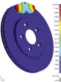 Brake analysis with MSC Marc. Image courtesy of MSC Software. |
Brake design and simulation aims to avoid failure under thermal or structural loading. The challenges start with material modeling; the makeup and properties of a typical brake pad are complex, and may be subject to quite significant variation across production batches.
A stochastic approach to modeling is increasingly important in automotive analysis, and this is a typical example. Understanding the implication of extremes and compensating for them avoids the odd rogue system—with its accompanying reliability and warranty issues.
Other brake analysis targets dynamic interaction causing brake squeal, judder and groan. Dynamic analysis of brake squeal traditionally used complex eigenvalue analysis, using a stationary disk on an isolated axle. Simulation now includes rotating disks and caliper action in the context of full vehicle response. Multi-body dynamics using rigid body simulation of the vehicle is linked to the flexible body dynamics of the brake system. Further inputs, such as an anti-lock braking system (ABS), can be included through the high-level system modeling approach.
Simulation of brake heating and cooling now typically includes thermal and CFD analysis of rotating, rather than simplified stationary models.
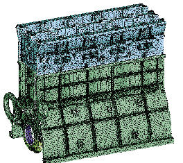 Powertrain durability model. Image courtesy of Altair. |
Tire Modeling
The performance and response of the road tires dominates much of the automotive simulation methods such as noise, vibration and harshness (NVH), handling and ride. These are all directly related to how the tire will respond—and clearly form a vital part of the chain, from road to vehicle component.
Tire modeling has progressed from simplistic doughnut- or spoke-type models that modeled basic stiffness parameters. Current simulation technology is attempting to model the tire under a wide range of operating conditions, including sideways or lateral shearing, and rolling actions with resultant heavy distortion of the tire, partial lift-off and other scenarios typical in the real world.
The tire is a complex assembly of advanced material components. Many of the ingredients are hyper-elastic in nature, meaning they respond differently in tension, compression and shear. That means a great deal of careful tuning with test analysis correlation to make sure the fundamental response is well modeled.
Other challenges include bond-line failures, heavy distortion and localized heating. The influence of the pressure inside the tire walls requires coupled fluid and structural modeling. In addition, the dynamic interaction between the rim and tire is important.
Tire analysis also has to be conducted in the context of the overall vehicle response—and, as with brakes, multi-body dynamics links structural and system models.
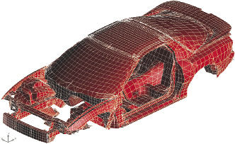 Automotive optimization simulation. Image courtesy of MSC Software. |
Of course, automotive manufacturers are not in the business of manufacturing and designing tires. There may be many tire options across the range of vehicles a manufacturer offers. The emphasis on tire modeling for development lies with the tire manufacturer, but commercial confidentiality limits how much model More Information can be shared. The full burden on modeling the tire in the context of the vehicle safety and performance lies with the vehicle manufacturer.
NVH Concerns
NVH embraces many vehicle components and physical disciplines. One of the major areas here is the study of the acoustic response of the vehicle. There are several sources of noise within the vehicle—the tires, transmission, power plant, external airflow, etc. These inputs are transmitted through to the body and, of particular concern, to the glass window surfaces.
Acoustic analyses are carried out to determine the interior noise levels that the occupants will experience. This requires coupling the structural model of the vehicle to a CFD model of the internal volume, and tracing the acoustic transmission path. Sound-absorbing features such as seats, carpeting and acoustic liners are all modeled within this environment.
Much of the noise is characterized by high-frequency content. This becomes a very demanding analysis, as a large number of modes are required with high fidelity of mesh to capture the short wavelengths of the structural response.
Engine and Powertrain
Other vital areas to simulate include the engine and powertrain components. Each demands its own variety of disciplines to fully understand the real-world physics—and hence, how to simulate and improve design.
For example, the engine is a complex assembly of static and moving parts that are taking in air and fuel, producing exhaust products and delivering power to the transmission. Overall dynamic and thermal modeling of the response of the engine is important.
In addition, detailed assessment is required in many areas such as the stresses within the piston, cylinder head and valves during each power cycle. This involves a multi-discipline approach involving thermal, combustion, structural and fluid dynamics interactions.
An initial analysis of engine components such as the piston and connecting rod may take “frozen” positions with pressure and inertia forces in a pseudo-static balance. More sophisticated, full transient analysis can add dynamic and thermal effects.
Predicting dynamic interaction is a key requirement in many systems throughout the engine and powertrain. The transmission of power through torque converters, etc., requires careful attention to avoid damaging dynamic magnification or resonant frequency excitation. The exhaust system must be designed so that inadvertent dynamic coupling between engine block and body mounting does not create unpleasant vibrations.
Durability Issues
Durability of vehicle components is essential to provide a long service life and minimize warranty claims. Successful implementation of durability analysis using fatigue and fracture mechanics analyses requires a thorough understanding of the characteristics of the material, the component and also of the loading scenarios.
The magnitude and sequence of loading on components is vital in fatigue analysis. The history of suspension, steering systems and drivetrain is difficult to assess. We, the drivers, are the huge uncertainty in the loop—with no such thing as a “typical” operating envelope.
Compare a rental car subjected to a history of abusive and aggressive driving (in the engineering sense) with a one-owner commuter vehicle. The challenge is to embrace all these situations. Interesting future developments include onboard fatigue monitoring and “weak links,” which will safely demonstrate a component is overloaded by sensors or permanent deformation, but can be easily replaced.
What is clear from talking to automotive manufacturers is that goals are moving beyond the minimum requirements of safety, handling and acceptable driver comfort. An ever-increasingly competitive market means manufacturers strive to deliver a quality of experience that will excite the customer.
Simulation is playing an ever-stronger role in making this achievable. Traditional disciplines such as crash are getting more sophisticated, and new disciplines such as MP, multi-body dynamics and full-system modeling are developing important roles.
Tony Abbey is a consultant analyst with his own company, FETraining. He also works as training manager for NAFEMS, responsible for developing and implementing training classes, including a wide range of e-learning classes. Send e-mail about this article to [email protected].
More Info
Subscribe to our FREE magazine, FREE email newsletters or both!
Latest News
About the Author
Tony Abbey is a consultant analyst with his own company, FETraining. He also works as training manager for NAFEMS, responsible for developing and implementing training classes, including e-learning classes. Send e-mail about this article to [email protected].
Follow DE

