The Art of Idealization in Finite Element Analysis
There's an incorrect tendency to think of a highly detailed CAD model meshed with a large number of elements as the "real" structure. It is important to remember that every FEA is an idealization of the real world.


April 1, 2013
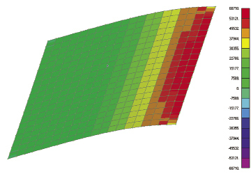 Figure 1: Top and bottom fiber stresses under bending. Figure 1: Top and bottom fiber stresses under bending. |
Idealization in finite element analysis (FEA) is the art of taking a real structure and reducing it down to an assembly of finite elements. At its simplest level, the operation would consist of a single geometric model produced from CAD and fully meshed in one operation. This gives us a consistent mesh throughout the structure that we hope will adequately represent the response of the real structure.
The FEA method relies on a set of discrete finite elements to represent the structure. Each element has its own basic “understanding” of what constitutes a structural response. This may be a very primitive representation, such as a 1D rod with a constant axial force, or a sophisticated 3D element. The discrete representation suffers from two fundamental weaknesses: By definition, it can’t be a continuous representation, and it is also reliant on the accuracy of the element. Most elements are now mature, stable entities—but their performance and limitations should still be understood.
Why not just use 10 million elements?
If we have elements that are sufficiently accurate and we can put sufficient numbers in, is there any need to idealize?
Well, there are quite a few reasons why we may want to consider idealization in favor of just pouring elements into CAD geometry. The first question to ask: Is the CAD geometry an adequate representation of the structure?
By many definitions, the CAD geometry is the structure, so it may seem a surprising question. However, what we are really asking is: How does the structure respond, and will the geometry be able to support elements that best simulate that response? Solid elements may not be adequate unless we use unfeasibly large numbers.
In a static analysis, the structure has applied external loading and develops internal load paths to carry this to an adjacent structure or to ground. Understanding of the load path can be quite tricky.
The definition of the load application and grounding regions are also an idealization judgment. The internal load path will be affected by our choice of element type and numbers. If we make poor choices, we may find that the FE model doesn’t behave in the same way that the actual structure will.
2D Shell Elements
A classic example is a structure that is relatively thin and is designed to transmit bending loads. Water tanks, building floors and walls, ship hulls, aircraft wings and fuselages are common examples. A stress gradient exists through the thickness of the shell or plate. If we use Engineers Theory of Bending and Shear through a plate or beam, we can visualize what this stress distribution looks like. There are a class of elements that are designed specifically to handle this type of structural configuration and its structural response. These are the 2D plate elements that are found in most FE solvers.
So we have a structural configuration, a structural response and an ideal element to handle it. The difficulty arises in that the element is a purely 2D entity. It means we have to think about idealizing from 3D geometry to 2D layout.
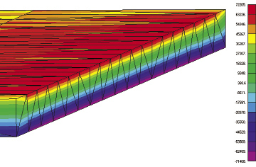 Figure 2: Single-depth Tet10 mesh under same loading, axial stresses. |
If the structure comprises all thin shell or plate, then there are relatively straightforward procedures to shell mesh. This may involve using mid-surfaces, inner mold lines or outer mold lines as the datum plane on which to put the shell mesh.
If the geometry is straightforward and the component count is low, this can be done fairly quickly. However, many structures are a complex intersection of components, such as pressure walls, internal ribbing, supporting structure, etc. It can become rapidly more labor-intensive to mesh such a structure.
Fig. 1 shows a simple plate structure, cantilevered from one edge with a pressure distribution. A shell mesh gives a peak bending stress and tip deflection very close to theory.
Fig. 2 shows a Tet10 mesh that gives good deflection values, but poor stress values. The mesh is only one element deep. To get accurate stress values, the element mesh needs to be about three deep. To avoid high aspect ratios, this drives the element count up toward 1 million, vs. 400 for the shell mesh.
If the structure has regions that are “thick”—where solid elements are ideal—and some that are relatively “thin,” where shell mesh is preferred, we have to now mix the meshing types. Many engineers don’t like to do this, because of the difficulty of dealing with the mismatched elements.
Special precautions are needed when putting solid elements adjacent to shell elements. Shell elements have six degrees of freedom (DOF) at each node, and the solid elements have three DOF at each node. For common nodes connecting the element types, this means that we have a piano hinge created. The connecting solid cannot transmit bending or torsion.
There are ways around this issue, such as overlapping shells onto solids, special connector elements allowing transmission of the moments, and linear glued contact regions to bond an overlapped dissimilar mesh. However, they require additional effort to plan and set up.
1D Beam Elements
Sometimes the structure is predominantly a flexural or torsional member—in other words, a beam type of structure. Examples include drive shafts, bridge girders, stiffeners and frames. In these cases we again have a class of elements ideally suited to this type of structural response and load path—beam type elements. They are 1D in nature, and we are using them to idealize a 3D real structure.
If, for example, we are looking for an overall assessment of strength and stiffness in a fabricated truss roof, it would be difficult to justify going to 3D solid elements. The geometry may well be a 3D CAD model, but if we were to mesh with 3D elements, the element count could rapidly become excessive.
Techniques for modeling such a structure with 1D beam elements are well established. We would typically take the centroid of each component cross-section and use that as the datum for our 1D element. Fig. 3 shows a simple beam structure modeled in 1D, with its base connected to a shell region via a spider element.
For a general structure, we may have a mix of beam-like, shell-like and solid regions. Fig. 3 shows a mix of 1D and 2D. This is often where a beam representation is avoided in favor of a full solid mesh.
For example, I have seen the rudder and rudder shaft of a ship fully modeled with solid. This gave nearly 2 million DOF in total, with half going to the rudder shaft and half to the fabricated rudder.
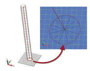 Figure 3: A 1D beam element. | 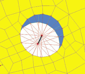 Figure 4: 1D/2D idealization of a bolted joint in a plate. |
The shaft is an inappropriate use of solid elements. The shaft is fundamentally responding in bending and torsion. What do we want from the structural analysis of the shaft? A shear force bending moment and torque diagram. This tells an engineer everything he or she needs to know about the response of the shaft. Having a solid component of 1 million DOF really doesn’t help us.
We can look for hotspot stresses and hopefully these will be meaningful, but if we have many load cases and want to justify why and where these hotspots are occurring, then we are in for a lot of work. We essentially have to backtrack to the shear force, bending moment and torque diagram in each case to demonstrate how the stresses occur and confirm their values. We have made a very straightforward task complex.
Connection Elements
Another common problem with a predominantly thin shell structure is how to represent the joints or connections. The CAD model will probably not attempt to represent welds as continuous geometry. It is quite adequate to define the connecting plates and to indicate the weld symbolically.
We don’t need to have a 3D geometric CAD representation of, say, a partial penetration fillet weld. However, when we want to create an FE model, we have to put in a structural idealization of the load transfer path through the weld. It may be that the best way to calculate stresses locally in the weld is to do this outside of the FEA, using local stresses or forces in an external program.
Similarly, we don’t want to model all of the bolts, rivets, etc., as solid elements. Fast and efficient ways of idealizing bolt stiffness and strength are available using beam elements and the very versatile “spider” connection and load distribution elements. Fig. 4 shows a spider element and beam elements being used to transmit load through a bolt.
Spider elements are useful in many scenarios, such as representing a stiff part of a structure with a rigid spider, or representing a load transfer path with a flexible spider. A future article will look in more detail at this type of element, as its uses are widespread and the terminology varies greatly.
Facing a Complex Future
I personally believe that if we’re not careful, the future direction of FE modeling will bring huge models of the order of 1E9 to 1E12 DOF, where all structure is modeled with solid elements from CAD. We will have to sift through the post-processed data and try and find local stress hotspots. Once we’ve found the local hotspot stresses, our next job as engineers is to explain why and how the stresses get there—and then advise how to improve the design. That is going to be the challenge. A good idealization can help us picture why and how these load paths exist. DE
Tony Abbey is a consultant analyst with his own company, FETraining. He also works as training manager for NAFEMS, responsible for developing and implementing training classes, including a wide range of e-learning classes. Send e-mail about this article to [email protected].
More Info
Subscribe to our FREE magazine, FREE email newsletters or both!
About the Author
Tony Abbey is a consultant analyst with his own company, FETraining. He also works as training manager for NAFEMS, responsible for developing and implementing training classes, including e-learning classes. Send e-mail about this article to [email protected].
Follow DE

