

July 2, 2012
By Kenneth Wong
When working in a CAD program’s modeling window, you usually have several display options. The simplest option provides you with basic geometric volumes and outlines. This Spartan option shows you the curvatures and edges of your design—and nothing else. As you turn on other details—such as hidden lines, shading, ground plain shadows, and reflections—the assembly in your modeling window begins to acquire more realism.
In a few CAD programs, you can turn on real-time ray-tracing in your interactive modeling window. With real-time ray-tracing, the term “photorealism” takes on new meanings, as the process uses complex algorithms to calculate light bounces to project shadows and reflections in a way that’s consistent with how they would appear in the real world.
No doubt you’ve heard the saying “the devil is in the details.” In CAD, with every detail you turn on, the devil exacts a tax in performance. Projecting shaded volumes, casting realistic shadows and showing reflections on surfaces consume a tremendous amount of computing power. The price you pay to be able to view your assembly in that mode is slower system response.
You’ll notice a lag, for instance, in model rotation and geometry rebuild after an edit. In real-time ray-traced mode, whenever you make a change to your CAD model, your system must recalculate on the fly the interplays of lights, shadows and physics to re-render your on-screen view, down to the smallest details. With such heavy demands, an older or slower system will have a hard time keeping up with your commands, creating jerky animations and temporary pauses.
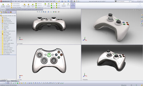 |
| When working in interactive mode, minimizing the size of the rendered viewport (top right view in this example, shown in SolidWorks 2012 with a four-viewport setup) gives you the ability to see the design in a realistic, shaded mode without a heavy burden on your CAD performance. A full-size rendered view, by contrast, could strain CPU and GPU resources, compromising your interactive CAD operations. |
With multicore workstations equipped with powerful GPUs, many designers and engineers now have enough—not more than enough, but just enough—computing horsepower to visualize their design in progress in a realistic, photorealistic or ultrarealistic (ray-traced) mode. Even so, with large assemblies or complex parts, turning on ray-tracing while you’re still heavily editing your design could put a burden on an average workstation. Until hardware becomes powerful enough to make the demands of rendering irrelevant, the best approach may be to balance the interactivity you desire against the realism you need.
The Tax You Pay for Shadows and Reflections
Among CAD software makers and users, the view on working in rendered mode or ray-traced mode is mixed. Some believe the performance penalty is too high; therefore, a more sensible approach is to perfect your design first, and then render it. Others believe the aesthetic appeal of a design is important enough that the interactive CAD modeling environment should offer a way to instantaneously render the design in progress.
Pete Lord, senior product manager for Autodesk’s Design, Lifecycle and Simulation Product Group, observes that “Autodesk Inventor users use in-CAD rendering for quick images to support customer and design reviews, and to check appearance prior to sharing with graphics teams.”
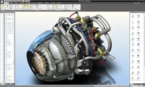 |
| Integrated real-time rendering in IronCAD, shown here with shadow mapping, shadow planes, reflection planes, bloom effects and hemispheric lighting. |
Paul Sagar, PTC’s director of product management, points out that while important, photorealistic rendering is not as necessary as real-time rendering. “Users want to feel more immersed in their design and be able to see a product look more realistic.”
Kris Kasprzak, Siemens PLM Software’s director of marketing for Solid Edge (SE), reports that generally speaking, most users turn off details like shadows and reflections. “They want to be able to see the geometry, see an unobstructed view of the design,” Kasprzak says. “The only time they go to what I call ‘the pretty picture mode’ is when they need to generate an image for a customer or a sales presentation.”
Carry O’Connor, IronCAD’s vice president of marketing, agrees. “The majority of design engineers don’t use realistic or real-time rendering effects,” O’Connor says. “But when they need to communicate the design, they may turn it on and send ]a rendered image] off to whoever needs to preview that concept.”
Xavier Melkonian, Dassault Systemes’ director, CATIA Creative Design, says interactive ray-tracing inside the modeling environment is important to CATIA users because “visualization must be part of the creative experience to have an efficient creative loop between the 3D shape creation and the visual result. But also because doing visualization outside of your 3D modeling environment requires a lot of data conversions and preparation, which is very costly and time consuming.”
“Two to three years from now, when hardware can support modeling with real-time ray tracing, people might work in that mode, but only if it accentuates the modeling experience,” predicts Mark Biasotti, SolidWorks’ product manager. “They won’t do it just because they want to look at material reflections and textures. Modeling is all about forms.”
The advantage of working in a rendered or semi-rendered mode in the CAD modeling window is the ability to edit your design and see a photorealistic update instantaneously. If you’re working in a fully rendered or ray-traced mode, exporting what you see in your modeling window as a common graphics file gives you a high-resolution, print-quality image. Therefore, you no longer need to initiate a rendering session to create a rendered image.
But the downside of working in a fully rendered, photorealistic mode is the increased computing demand, which affects how quickly your system can respond to your commands. In older, slower systems with insufficient processing power or memory, working in such a display mode is generally not recommended—or not possible at all.
Design and Render? Or Design First, Render Later?
Usually, if you’re in the CAD modeling window, you’re probably still refining your geometry. Therefore, you’re more concerned with shapes and measurements, and less concerned with the visual appeal of your design. You won’t, for instance, need to render a photorealistic view of your design each time you rotate to a new angle or add another hole.
This assumption remains true for the most part, for most CAD users. If you work with products that require constant attention to surfaces and curvatures—particularly, how they would look in the real world or how they interact with light—you may belong to a specialized discipline. This could be the case if you’re designing, for example, high-end perfume bottles, costume jewelry or headlights in luxury vehicles.
To separate design and modeling operations from rendering operations, most CAD programs give you the option to render outside the modeling environment. That means when your design is at a stage where you’re inclined to judge its aesthetic appeal or show a client an impressive image of your concept, you may invoke a rendering window—which usually appears in the foreground. This usually launches a rendering process that runs a few minutes (or a few hours, if you have an extremely complex scene to build, but a very slow machine) to generate an image of your design with lights, shadows, material textures and a background.
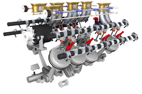 |
| Photorealistic rendering of an engine, created using Solid Edge’s rendering application. |
If you’re running a system with limited computing horsepower and you need to, from time to time, check your design’s aesthetic appeal or visualize it in a real-world setting (say, on a kitchen counter or a factory floor), you may be able to minimize the rendering operation’s impact by reducing the preview window’s size (the smaller the image, the fewer the pixels to calculate).
On the other hand, if your aim is to create a high-resolution still image, you have no choice but to relinquish a fair amount of computing power to the rendering process. While rendering is in progress, you may continue to refine your design, provided your system still has sufficient horsepower and memory left to support your normal CAD functions. Otherwise, your design operations may have to be suspended while rendering is in progress.
The other option is to export the file to a specialized CAD-friendly rendering program—like Luxion’s Keyshot, Luxology’s modo or Bunkspeed’s SHOT—to create a glossy still image or animation sequence. Some rendering software developers have released CAD plug-ins. If there is one that supports your preferred CAD program, you can initiate the process from within your CAD modeling window, bypassing the need to export a file and open a new program.
Dedicated rendering software usually produces better results than what you would get from rendering in a CAD program itself. For a start, a specialized rendering program gives you more choices in materials and preloaded environments (prebuild backgrounds you can drop your objects into), more flexibility in camera placement, and more control over the scene itself (to adjust darkness, brightness, fading distance, etc.).
For CAD programs that don’t have a built-in realistic display mode or rendering option, exporting to a renderer is the only option to get an aesthetically appealing image of your design. However, that’s now a rarity, as almost all contemporary CAD programs give you at least some type of tools to produce a nice-looking (or semi-rendered) image from your program.
Common CAD Modelers’ Approaches
With a robust software portfolio servicing the media and entertainment market, Autodesk offers you the option to work in real-time, ray-traced mode inside its mechanical modeler Autodesk Inventor. (Under View, along with visual styles, ground reflections and shadows, you’ll find the option to enable ray tracing.) Working in this mode, you have the option to set your preference to Interactive, Good or Best. The Interactive option is configured to provide the best possible ray-traced visuals on screen without hampering your interactive CAD operations.
RapidRT, the rendering technology driving Autodesk Inventor’s realistic display mode, is also found in Autodesk Revit (an architecture modeler) and Autodesk Showcase (a renderer program with a straightforward interface, included in many Autodesk suites as a standard component).
“RapidRT uses all available CPU cores on the system, and does not use the GPU,” Lord says, noting that OGS, the other Autodesk technology for visualization, responsible for shaded modes, wireframe, illustration and watercolor-look “uses the GPU and can use the CPU for software rendering if necessary.”
SolidWorks lets users launch a rendering session with PhotoView 360. It also offers the option to work with an integrated preview window, which effectively turns your modeling environment into a rendering preview window.
SolidWorks PhotoView is based on Luxology’s CPU-based rendering technology (the company behind modo, a popular rendering and animation package). Whereas SolidWorks software itself only takes advantage of two CPU cores at the most in modeling operations, the PhotoView add-in can take advantage of additional CPU cores your machine can supply to cut down your rendering time.
In IronCAD, you have the option to work in a realistic mode in real time, powered by Tech Soft 3D’s HOOPS technology. Though not a ray-traced mode, the setting provides you with shaded volumes, reflections and shadows for enhanced realism in the interactive CAD modeling window. To obtain a ray-traced rendering of your design in IronCAD, you may launch a separate rendering window (with the shortcut CRTL + R). You may simultaneously launch more than one rendering window, in case you need to render the same design in multiple colors or from multiple angles.
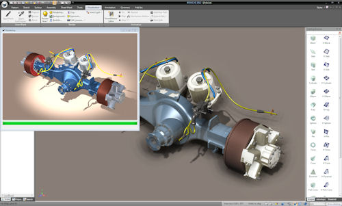 |
| For more sophisticated rendering, many CAD software programs offer rendering applications that can render still images with a preview window. The example shown here is in IronCAD. |
“The realistic rendering ]obtained through a separate program window] makes use of CPU cores. This is a multi-threaded operation, so it can take advantage of multiple cores,” explains O’Connor. “The real-time realistic mode ]which allows interactive work] makes use of both CPU and GPU.”
Similarly, Siemens PLM Software’s SE gives you the option to work interactively in an OpenGL-powered realistic mode. But to obtain a ray-traced rendering of your design, you’ll need to invoke a rendering session (under the Explode, Render, Animate tab), which produces simple animations in addition to still images. SE’s interactive realistic mode supports both CPU and GPU accelerations, according to Kasprzak.
In PTC Creo modeling products (Creo Direct and Creo Parametric), you can choose to work in OpenGL-accelerated mode, with shades and reflections turned on. However, this is not a ray-traced mode. In Creo Parametric, you have the option to produce ray-traced still images, but not to work interactively with CAD models. You may also use PTC’s Creo Advanced Rendering Extension to produce ray-traced images. Ray-traced rendering in PTC Creo products are powered by mental ray from mental images, a division of NVIDIA.
Dassault Systemes’ CATIA V6 software suite employs the company’s own technology and NVIDIA’s CGfx shaders. Two years ago, the company introduced a new rendering tool called CATIA Live Rendering, based on NVIDIA’s iray engine, to provide interactive ray-tracing and global illumination. iray takes advantage of both CPU and GPU cores. With CATIA Live rendering, the user can choose to use both CPU and GPU, only CPU or only GPU. As a legacy of of CATIA V5, Dassault Systemes also provides the option to render in NVIDIA’s mental ray.
“CATIA Live Rendering is totally embedded inside the modeling environment, which means that at any time a user can activate this visualization mode and see his product ‘interactively’ with ray-traced shadows and reflections and global illumination,” says Dassault Systemes’ Melkonian.
If you prefer to work interactively in realistic or photorealistic visual settings, you should investigate whether your CAD software’s rendering engine can benefit from additional CPUs or GPUs, then upgrade your hardware’s processors and memory to accommodate such a workflow.
Dreaming of Ray-traced Interactivity
At the present, ray-traced interactivity—editing a detailed 3D model in ray-traced mode—is something of a luxury, simply because of the sheer power you need to preserve interactivity. Currently, designers and engineers occasionally turn on ray-tracing, but work in a less-ostentatious display style by default.
Next-generation workstations powered by Intel’s many integrated cores (MIC) architecture or NVIDIA’s Kepler architecture may change that. If the hardware provides so much computing power that rendering becomes an instantaneous (or near-instantaneous) process, they may work in ray-traced mode by default.
For now, though, shadows, reflections and textures still have a cost—payable in performance gain or loss.
Kenneth Wong is Desktop Engineering’s resident blogger and senior editor. Email him at [email protected] or share your thoughts on this article at deskeng.com/facebook.
More Info
Subscribe to our FREE magazine, FREE email newsletters or both!
About the Author
Kenneth Wong is Digital Engineering’s resident blogger and senior editor. Email him at [email protected] or share your thoughts on this article at digitaleng.news/facebook.
Follow DE

