The Right Fit
Interference problems solved, two parts can now work together.


Latest News
October 14, 2007
By Kristine Spangard
 GKS Inspection Services helped The Toro Company solve an interference problem between two rotor housing components — one made of a molded polymer, the other of stamped steel — for a new lightweight snowthrower. |
The Toro Company, which provides outdoor maintenance and beautification products for home, recreation, and commercial landscapes, was in the final phase of developing a new single-stage snowthrower when it ran into an interference problem between two large rotor housing components. One of the parts was made of an injection-molded polymer, the other was made of stamped steel.
Senior principal designer, Nathan Friberg, explained, “The design required major portions of adjacent surfaces on the two parts to align in order to assemble and function properly.”
The first parts of tooling were difficult to assemble because of interferences between the two parts. “To add to the complexity in solving the interference problem, the surfaces in question had large curved contours that were difficult to inspect,” Friberg added. Since both parts were already tooled, Toro needed accurate inspection data that could be compared to existing Pro/Engineer 3D models in order to determine where the interferences were occurring, and how to modify the tooling to get the parts to fit.
“We decided the best way to create the inspection data was to laser scan the parts, so we called Larry Carlberg at GKS,” said Friberg. GKS Inspection Services is a division of Laser Design, Inc., based in Minneapolis,MN.
The Solution
Toro, a repeat customer of GKS, was confident in Carlberg’s ability to quickly create excellent scan data to solve the fit problem between the snowthrower parts.
With more than 25 years in the business, GKS metrologists have experience with all kinds of custom projects. Carlberg explained the approach he would take and how to address the issues of the large curved contours. Because the laser-scanning system projects a line of laser light onto surfaces while cameras continuously triangulate the changing distance and profile of the laser line as it sweeps along, the problem of missing data on a curved surface is eliminated. The system measures fine details and captures complex freeform geometry so that the object can be exactly modeled. Laser scanners quickly measure articles, picking up tens of thousands of points per second, and generating huge numbers of data points without the need for templates or fixtures.
“Working together with Larry and the scanning technician, we discussed which surfaces to scan, how the parts should be set up, and the tolerances we were expecting from the scan results,” Friberg continued.
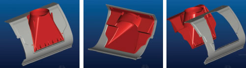 These different views of the metal snowthrower housing (gray) and its plastic insert (red),were created using a FARO scanning system with a Laser Design SLP330 laser probe.The parts were aligned by centering the fastener holes to simulate physical assembly.When the two point clouds were aligned, interference between the parts was immediately evident. Scanning and data editing (using Geomagic Qualify on a Dell 350) took four hours. |
Both of the parts were set up on a FARO scanning system with a Laser Design SLP330 laser probe. Carlberg elaborated on his method: “This setup provided a fast method to capture all the surfaces required with minimal time.” Carlberg performed three quick preliminary scans to determine the correct shape and placement of the two parts in relation to each other when they were assembled.
This trial-and-error mock assembly process aligned the housing to a manufacturing datum, ensuring that the snowthrower auger’s axis datum was in an acceptable position with respect to the rest of the housing. “When an assembly doesn’t fit together correctly it is difficult to determine where the interference is with the real physical parts because if you force them together you distort the shapes,” said Carlberg. “With the virtual scan data, we can overlay one part’s data with the other’s until they are aligned correctly in the model. The agility and quickness of using the portable arm system allowed us to do several test scans to verify acceptable alignment in just a few hours, even using a trial-and-error method of datum alignment.”
After the correct alignment was achieved, GKS scanned the rest of the housings, paying close attention to key areas, such as the critical mounting locations used to fasten the two parts together. Carlberg summarized, “Once we completed the scan of the steel rotor housing and the injection molded liner, the solution was quite simple. We aligned the parts by centering the holes used to fasten them together. This technique simulates the physical assembly that occurs during manufacturing.”
Carlberg then created surfaces from the data, focusing especially on the critical locations. “When the two point clouds representing each of the two parts were aligned by the holes’ centers, interference between these parts was immediately evident. We exported color-coded comparison reports to the Toro engineering team showing this interference.”
The Results
GKS completed the scanning and data editing with Geomagic Qualify on the Dell 350 in four hours. Before laser scanning was available, this process could have taken days or even weeks to complete. Freeform shapes such as the Toro housings would have been measured manually with calipers, a very labor-intensive and open-ended process. The interference could not be determined by forcing the actual physical parts together because of the distortion and stress it would create in the plastic material.
Many iterations of the manual trial-and-error measurement method would be needed to find a solution. Carlberg explained, “By using the virtual scan data of both parts’ surfaces, we could determine the interference locations and remove the inherent stress to the parts. With laser scanning and our sophisticated software packages, the Toro engineers had answers in four hours.”
The scan data indicated that both parts had significant areas contributing to the interference problem. Toro engineers were then able to download the scan data files directly into Pro/Engineer, and compare the results to the 3D models.
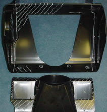 These rotor housings were scanned by GKS, a division of Laser Design, and are marked to indicate areas of suspected fit interference. |
Friberg clarified, “At this point we were able to see where the interferences were occurring, and determine the best method to solve the problem. Fortunately, we were able to make a relatively simple change to deepen the offset in the stamped steel part, which overcame the interferences caused by both parts.”
“The process was very successful for us,” concluded Friberg. The mating assembly holes in the initial parts were almost one-half diameter off, but by using the scan data, the engineers were able to correct the problem quickly and accurately before the pre-production pilot build and, more importantly, before the production process was online.
The original service plan called for GKS to perform another set of scans on the parts after the tooling had been modified based on the first set of scan data, but the results from the performed process were so successful that the Toro engineers did not feel a secondary scan was necessary to verify the tooling corrections.
They were right. According to Friberg, “We just completed the preproduction pilot build for this product, and are happy to report that the fit between both parts was excellent.”
More Information:
Faro International, USA
Lake Mary, FL
faro.com
GKS/Laser Design
Minneapolis, MN
gks.com
Geomagic, Inc.
Research Trangle Park, NC
geomagic.com
The Toro Company
Bloomington, MN
thetorocompany.com
Kristine Spangard is a technical writer based in Minneapolis,MN. She specializes in writing about 3D laser scanning, biomechanics, health, and medical topics. You can send an e-mail about this article to DE-Editorsmailto:[email protected].
Subscribe to our FREE magazine, FREE email newsletters or both!
Latest News
About the Author
DE’s editors contribute news and new product announcements to Digital Engineering.
Press releases may be sent to them via [email protected].


