

Latest News
September 4, 2007
By Pamela J. Waterman
 This diagram illustrates the calculated temperature distribution across a simple small heat-sink based on CFD analysis of effects from a fixed heat source. |
Whether you need to heat something up or cool it down, understanding the physics behind the challenge is key to finding a reasonable solution. Hand-calculations based on textbook formulations may be good enough, or at least set you on a path to choosing real-world coefficient values, but most engineers look to analysis software for help.
A common function in computational fluid dynamics (CFD) and thermal/structural software packages is that they can both perform thermal analyses. Some packages also display similarities at the mathematical level, relying on one or more combinations of finite elements (FE), finite differences (FD), and finite volumes (FV) in the underlying mathematics. However, fundamentally, they define two different realms of operation — solids or fluids.
Defining the challenge
George Laird, a seasoned consultant with Predictive Engineering (Portland, OR), explains that users must ask a basic question: “Is this a conduction-type problem within a solid, or a flow-type problem involving the movement of a fluid (gas or liquid) and its interaction with a hot or cold surface?”
In fact, Laird states that it is helpful to sit down and outline all expected thermal challenges such as conduction, forced convection, natural convection, radiation, and even solar radiation or joule heating. Today’s software packages often step you through evaluating and defining all these factors with wizard routines, making the task quick and straightforward for many combinations of materials and configurations, as well as allowing you to compare “what-if” design changes.
If you can describe the problem as involving a well-defined heat source or cooling fluid, and you simply need to know the change in temperature across a part or assembly, you can probably work with structural/thermal software. Or, if you need to understand mechanical stresses within a part, and predict thermal expansion between parts of different materials, again a structural analysis is a likely choice, and most such packages can handle the job.
Even if radiation is involved, there are also specialized packages that are set up in fine detail to do sophisticated thermal analyses, allowing for angular dependent surface properties and specular and diffuse surfaces. However, many consultants will say that for certain problems and requirements, additional factors come into play, and just looking at the solids’ point of view may not be sufficient.
| Capturing a Coefficient — The heat-transfer coefficient, h, is a material- and geometry-dependent value that determines how much heat flows across a boundary for a given temperature gradient. Some analysis packages will ask you to input a numerical value for this factor. The simplest way to do so is to look up an h value for a specific material in a handbook such as Heat Transfer by J.P. Holman (McGraw-Hill Education; 8Rev Ed Or, you can start with the basic equation, Q= hA (Twall - T`) and solve for h, where Q = rate of heat flow per unit area, A = surface area of the part being cooled/heated, Twall = temperature of the part at the surface, and T` = temperature of the air or fluid some distance away (or at infinity). You solve for a good h value by putting in your best guess for Q plus measured values for both Ts. For a part such as an electronic component, you may actually know Q from the manufacturer’s specifications. |
Digging deeper
A structurally based approach has to make some assumptions for setting up a problem, and this is where things can get tricky. The software models convection as a thermal load with a prescribed (usually constant) fluid temperature as well as a numerical film coefficient, h, (also termed the heat-transfer coefficient or convection coefficient), which must be user-defined (see sidebar).
According to Jim Radoccia, analyst at JLR Engineering (Everett, WA), the h value is by far the biggest unknown quantity in a structurally based thermal analysis. Radoccia points out, “It is dependent on a variety of factors such as fluid velocity, fluid properties, fluid temperature, and surface orientation (of the solid part).”
But simply using reference tables or calculating h from the basic heat-transfer equation neglects, for example, the fact that the fluid flowing over the hottest section of the part itself becomes hotter as it passes by, and therefore no longer has the same cooling capacity as it progresses across the part. Other factors influencing the accuracy of h include possible turbulence in the fluid flow (generated by the geometry of the part itself), the orientation of the geometry (for example, ridges on a finned heat-sink), the composition of the fluid, and the fluid velocity at different locations in the flow (again influenced by geometry). You may also need to add a term to account for convection.
Consultant Tyler Smithson, principal engineer at Smithson Engineering (Crestline, CA) notes, “A structural analysis may best be used when the heat source is well-defined, and the cooling fluid is fairly constant (flowing water or air around a part). Questions easily answered include: Can the part be changed to spread heat? Can a heat fin help dissipate the heat? Will longer fins do the trick?”
The fluid angle
If you’re not confident about calculating a decent thermal coefficient, you can take the fluid-flow approach to analyzing the heating and cooling of a solid. Equally important, if the temperatures are dominated by fluid flow — either natural or forced convection with a liquid or gas — CFD is the best choice; since a structural solution only solves for conditions within a solid, understanding any aspect of fluid flow requires actual CFD capabilities.
Engineers and analysts are increasingly realizing that if you neglect fluid effects, you may not be producing the most effective design. Roxanne Abul-Haj, principal engineer at ARA Engineering (Mesa, AZ) affirms that including all possible thermal effects can be extremely important. She says, “To determine the most accurate results, you should conduct a conjugate ]coupled] heat transfer analysis, combining the effects of radiation, conduction, convection, and any internal heat generation.”
Five years ago, the sheer complexity of a CFD analysis often made this task difficult, but today’s packages usually give even a designer-level engineer the proper tools. Very advanced software is available, letting you define a temperature gradient, variations in fluid density, rate of fluid flow, particles in the fluid and dozens of other factors. At the same time, designer-level software can also produce very detailed and acceptable results. The latter packages have wizard functions to step you through defining all necessary parameters, and will alert you if values you have chosen are outside of normal ranges or conflict with another factor.
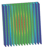 Calculated temperature distribution across a simple small heat-sink, based on structural FEA analysis of effects from a fixed heat source. |
Which way to go?
One way to increase the accuracy of a solid-based thermal analysis would be to collect empirical measurements on various similar geometries of prototype parts, and calculate an average value for h. This number would be more relevant than the textbook value based on material type alone.
Another improvement would be to choose a different convection coefficient-value for each fin of the heat-sink, to allow for the temperature gradient from the center of the heat source outward.
Lastly, just doing a better job defining the boundary conditions, perhaps including the effects of pressure, would improve the overall results.
Radoccia sees the biggest contrast between structural-thermal and CFD approaches in the fact that the former does not solve for anything within the fluid. He points out, “If you need to understand the behavior of the heated or cooled fluid, a CFD approach will give you temperature (distributions), plus velocities and pressures in all three directions. Depending on the particular package, you can also model any phase change and chemical reactions that result in endothermic or exothermic heat generation.”
Trade-offs
Life and engineering are full of trade-offs. FEA packages are generally less expensive and can be easier to use, partly because fewer users have been trained as much in the details of CFD. On the other hand, most CFD codes allow the thermal results to be exported to FEA codes for one-way fluid-structure interactions (FSI), or for looking at thermally induced stresses.
However, Laird cautions, “Many CFD tools try to do it all — they want to be FEA tools, or, when they couple ]such effects as] magnetic and chemical reactions, they add complexity and remove ease of use.”
So think about who will be performing the analysis, how the results will be used further by other users and other software, how often you will be doing this type of analysis, and whether a general-purpose or application-specific package might best suit your needs. It’s a hot topic around the water cooler.
Contributing Editor Pamela J. Waterman is an electrical engineer and freelance technical writer based in Arizona. You can contact her about this article via e-mail sent to DE-Editorsmailto:[email protected].
Subscribe to our FREE magazine, FREE email newsletters or both!
Latest News
About the Author
Pamela Waterman worked as Digital Engineering’s contributing editor for two decades. Contact her via .(JavaScript must be enabled to view this email address).
Follow DE

