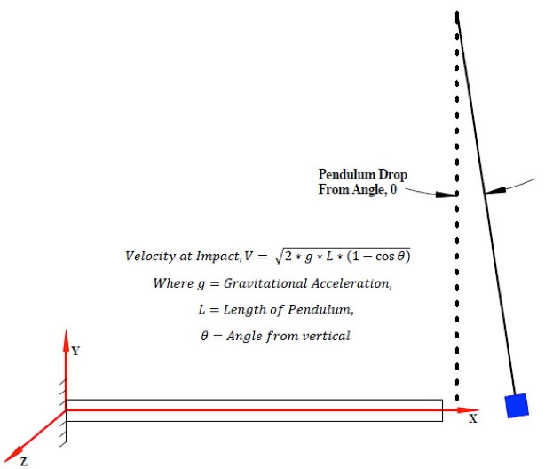
Fig. 1.2: Pendulum Drop Impact


Latest News
May 8, 2015
By David Dearth
The topic of this technical article is to predict the maximum impact stresses produced when a concentrated mass, traveling at constant velocity, impacts the end of a uniform beam or rod. In future issues I will expand on this simple transient dynamic impact response problem and graduate to impact problems where rebound is included in the nonlinear, transient, dynamic impact solutions and later to impact with penetration.
Introduction
There are many circumstances upon which a concentrated mass may impact a structure. Three common conditions in which a concentrated mass may impact the end of a beam are the following:
- Figure 1.1: Dropped from a known distance or height
- Figure 1.2: Dropped, or allowed to rotate, through a known angle as in a Pendulum drop test
- Figure 1.3: Traveling at a constant velocity
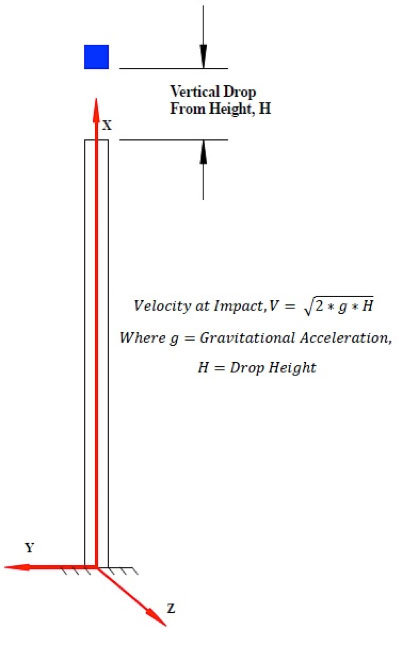 Fig. 1.1: Vertical Drop Impact
 Fig. 1.2: Pendulum Drop Impact
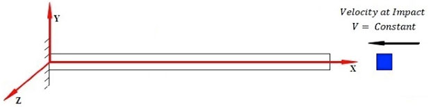 Fig. 1.3: Constant Velocity Impact
Peak Compressive Stress Due to Impact
In most cases where impact conditions occur, it is desired to compute maximum deflections and stresses during the transient response after impact. The first approach to the solution for maximum stresses can be computed by assuming the impacting mass stays attached or sticks to the impacted body and does not rebound or bounce off when the compressive wave is reflected back to the point of impact.
Consider a simple uniform beam or rod impacted by a concentrated mass. The exact solution from solving the differential equations to compute the maximum compressive stress, σmax, due to a concentrated mass Wm impacting a uniform rod of mass Wb, at known velocity is the following (Reference 2):
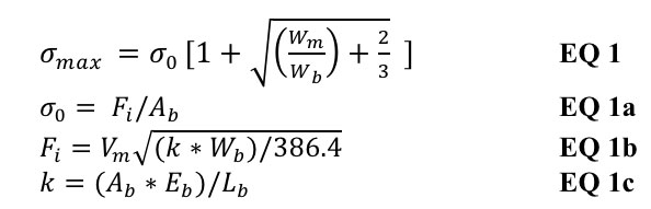
Where σ0 is the initial stress resulting from the suddenly applied impact force uniformly distributed over the beam or rod cross sectional area. The limitations for EQ 1 through EQ 1c assume stresses due to impact are distributed along the length of the rod similar to linear static loading. Under actual impact conditions this assumption is unattainable.
Sample Problem: Uniform Rod Impacted by Concentrated Mass Traveling at Constant Velocity
Fig. 2 shows a sample problem selected to investigate transient impact solutions. In this simple example, a uniform rod is impacted by a concentrated mass traveling at a known velocity at impact. The problem is to compute the peak compressive stresses during the transient response of the rod free end.
For our sample problem, it is desired to estimate the peak compressive stresses due to the impacting mass during one complete cycle of the compression wave before the mass bounces off the Rod free end.
For this sample problem, it is assumed the striking mass will not bounce off the end of the rod. Our solution will be valid for one complete wave reflection. In the actual case, after one complete reflection of the strain wave (compression in this case) the mass will bounce off from the rod-free end. This sample transient problem contains all the features of any real-life problem and can be found in engineering literature in just about any text that addresses impact.
To gain confidence in our solution, we will present two approaches: (a.) hand solutions using conventional equations found in most engineering textbooks on impact problems and (b.) correlate results with a finite element idealization using Nastran FEA (finite element analysis) code. (Editor’s Note: The detailed hand calculations for estimating peak compressive stress due to transient impact may be obtained by contacting David Dearth through email.)
For the Rod/Mass system shown in Fig. 2, assume the rod length is L= 24 in. and the rod cross section is a circular section d = 1.0 in. The concentrated mass weight, Wm= 50 lbf, and impacts the free end of the rod at velocity, V0 = 40 in./sec. Compute maximum compressive stresses during the transient response after impact.
 Fig. 2: Simple Impact of a Concentrated Mass Traveling at Constant Velocity.
When performing these transient nonlinear impact analyses, one difficulty novice FEA analysts confront is ensuring they have performed all the necessary tasks to predict maximum deflections and stresses and to generate the correct time history response. The answer to this question is taking the time to do these sample problems. These sample FEA problems should be such that you can compute a known theoretical solution. With a sample problem and known solution, analysts can have a detailed hand sanity check that is completed using a pencil, paper and a calculator. If analysts cannot solve simple problems using a computer, that can be solved using hand calculations, then how can they have confidence in begin able to solve their real problems using a computer?
The perspective to keep is that the same steps that analysts must jump through to solve this simple rod-mass-impact system are the same steps needed to solve the real-life problem using the computer. The only difference between the FEA approach and the hand solutions are usually the complexity of the geometry.
Answers
The exact solution from solving the differential equations for predicting the transient response for the model shown in Fig. 2 can be found in Reference 2 and 3. The theoretical exact solution for maximum compressive stress at the rod tip gives σmax-exact= 24,716 psi. Fig. 3 shows the transient dynamic time history plotting results from an FEA model idealization of Fig. 2 processed using Nastran. In Fig. 3, a 20-element FEA model solution predicts maximum tip compressive stress σmax-FEA= 23,480 psi. A comparison to the theoretical exact solution gives a percent difference of ±5.0%.
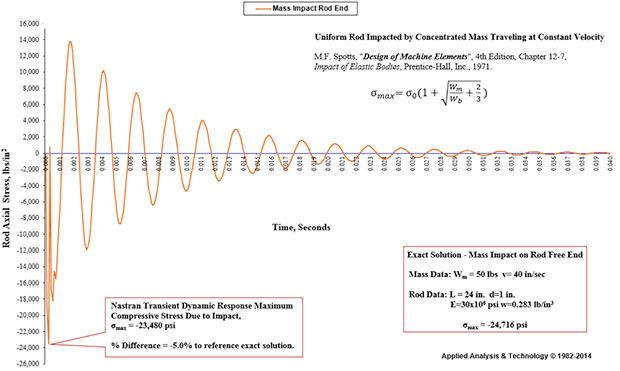 Fig. 3: Summary Results FEA Solution – Uniform Rod Impacted by Concentrated Mass/Time Dependent Response to Initial Velocity at Impact.
Documentation
References
- F. Spotts, “Design of Machine Elements”, 4th Edition, Chapter 12-7, Impact of Elastic Bodies, Prentice-Hall, Inc., 1971.
- Eugene A. Avallone & Theodore Baumeister III, “Marks’ Standard HDBK for Mechanical Engineers”, 9th Ed.” McGraw-Hill Book Company, 1987, page 5-47, 5-48 Impact.
David Dearth, P.E., is with Applied Analysis & Technology Inc. in Huntington Beach, CA. Contact him via [email protected].
Subscribe to our FREE magazine, FREE email newsletters or both!
Latest News


