

Latest News
March 3, 2008
By Al Dean
 NC Optimiser is a postprocessing tool that executes after NC code has been generated, performing a real-time analysis of forces on the machine tool (feed rate); compares it with the stock left on geometry;and optimizes the feed rate accordingly. |
There is a clear split in the vendors operating in the CAD/CAM industry. There are general-purpose CAD tools providing basic CAM support and then there are those heavily engaged in the production environment developing tools to solve real manufacturing issues. One of the leaders in the latter category is UK-based Vero Software. The company has been building its depth of knowledge and impressive level of detail in process and task support for the mold, die, and machining industry for the past three decades.
The system covers everything from 2D and 3D CAD (it was the first system to implement Parasolid on the Windows platform) to mold, die, and electrode design and analysis, as well as a whole host of machining covering everything from 2.5- to 5-axis milling. Of course, when you have a system with such breadth of functionality and knowledge built up over many years, you also find that the user experience starts to suffer. So, with this in mind, Vero began a process of looking at the system a few releases back, improving it and bringing it up to date with a complete reworking of the interface. This updating has been extended to areas such as geometry definition, modification, and manufacturing-process support.
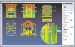
As a result, today’s VISI interface is clean and fresh, which helps with initial training. It supports all modern requirements in terms of graphic display and functional dual-monitor support (something big-name CAD vendors haven’t yet got right).
Specific updates
At the base of the UI, you’ll find a small text entry box. This allows you to quickly type in a search string that pops up a list of commands that match that string. For example, typing BLE will give you all of the blending commands.
Geometry display has also received much attention. Plus, reflection mapping is now available, allowing you to use any bitmap image or industry standard zebra striping for surface evaluation. On the same subject, threaded holes are now displayed using a threaded bitmap representation, which is going to be really useful for those designing complex molds: It’ll be immediately clear whether a hole is threaded or not. You can also customize the colors of specific hole types to make design data less ambiguous.
There are a lot of updates to make your displays more efficient, such as quality control, more powerful dynamic sections with controls for capping and hatching sectioned faces. Finally, you can display a model at 1:1 scale (you input your screen size and it adjusts) and you can display the models in perspective mode.
Modeling tools
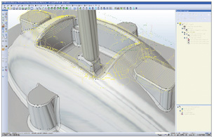
VISI is a hybrid modeling system — as any system for the mold and die industry should be — so you can create and modify both complex surfaces and solids equally. An interesting new feature is Drape Surface. Draping surfaces is available in other systems, where a surface is theoretically dropped onto a collection of points or surfaces to create a single skin that covers the entire form. But the VISI version differs in that it allows you to work with more complex parts. Specifically, it works with complex surface skins with multiple holes, open loops, and the like as is typical in the automotive industry and with Body In White in particular. You select the geometry, the direction of the drape, and how the system builds the surface (in terms of matching to the boundary edges and maintaining tangency). The surface looks like it could solve those really tricky surface-patching jobs that always give you a headache and require a lot of manual work.
Another new surface tool is Large Offset, which is useful in the die industry where it’s common to create large offsets (60mm and up) from complex forms at the back of a die to save weight. This can cause problems where surfaces intersect or twist. The Large Offset command enables you to tessellate the surface, creating an offset from that mesh, and then resurface the resultant face. While this might not be accurate, the fact is accuracy isn’t critical. While on the subject of offset surfacing, you can now create a variable offset surface where individual parameters are added for each UV point. This might seem a little esoteric, but I’m sure some customers will use it; particularly those in the shoe industry.
|  The new Large Offset lets you create complex offset surfaces over large distances and, while aimed at the die design market, should prove useful toother users for whom geometry accuracy isn’t essential. |
There are three other modeling updates. Creating split lines and run-off surfaces is now much easier as Vero has formalized a former workaround that allows you to create both the outer boundary of the parting surface quickly (by offsetting the parting curves) and then automatically create and merge the run-off surfaces. You can now mix and match with surface edges and wireframe (non-associative) geometry to create an N-sided patch. Finally, a Parasolid problem — where merging surface sets have a tendency to remove edges that might be required in downstream processes — is solved. By using the Mark Edges operation, the system is aware that those edges need to be maintained and will protect them in any further merging operations.
Documenting and drafting
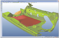
VISI is a pretty impressive tool for documenting manufacturing data — as you’d expect. This release includes four major advances. As with many applications, you can now create shaded views within drawings and have the full range of extended controls available in the modeling environment. You can now create variable section views with control over breaking line display style and can also create isometric views of those variable sections that are incredibly useful for documenting the internal forms of mold assemblies, etc.
You can automatically create ordinate dimensions by simply selecting the data and the system will dimension all holes and such, even trimming back intersecting leader lines. Finally, there’s a new tool called CAM string. Essentially, when you add a hole in a 3D model, machining intelligence is built into the feature. Unfortunately, when it comes to documenting that hole, you might have a specific way you want it to be documented. Using the CAM string command, you can add your own custom strings, add information you want, and link to automatically extracted feature information (depth, thread count, etc.). This can then be extracted in dimensions and holes tables.
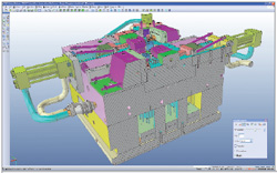
Machining + CAM
VISI is a more-than-capable CAM system, providing support for all the major variants of machining from 2.5-axis production to high-speed 3-axis machining and more. This release includes key work in machining operations and optimization of NC code.
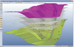
On the operations and strategies front, the handling of complex forms featuring steep and shallow geometry in a single part has been improved. There’s a new Steep and Shallow strategy that allows you to mix and match toolpaths to handle both types (typically waterline for steep areas with 3D stepover operations for shallow areas) of geometry within a single contiguous toolpath. This results in a performance and preprocessing benefit as well as surface quality improvements.
  Variable section views are now available with full control over breaking line display style. Isometric views of those variable sections can also be created. |
The major new tool is NC Optimiser. This is a postprocessing tool that executes after NC code has been generated. It performs a real-time analysis of forces on the machine tool (feed rate), compares it with the stock left, and optimizes the feed rate accordingly. You add minimum and maximum feedrates, the system will then analyze the toolpaths, and then ramp up feed-rates where there’s less load on the machine (or reduce it for higher loading conditions).
 The new Steep and Shallow strategy allows you to mix and match toolpaths to handle both geometryconditions within a single contiguous toolpath. |
VISI represents an impressive set of applications for those immersed in the world of manufacturing, whether that’s mold and die design, progressive die development, or more production-oriented machining. The whole system looks modern and fresh thanks to the work done over the past few releases to enhance the interface.
What I find most interesting is the NC optimizer and how it relates to the rest of the system. In the manufacturing world, time is key. You receive a job and the time you take to produce parts, whether end-use components or a mold or die, doesn’t matter. What matters is that you make delivery. And when you’ve got the right tools, time can be saved everywhere.
VISI is one of those tools. It allows you to improve quality in less time and more efficiently. It’s a compelling solution for anyone involved in complex product manufacturing.
More Info:
Vero VISI V15
Vero Software
Gloucestershire, U.K.
vero-software.com
Contributing Editor Al Dean is the former technology editor at MCAD Magazine, a UK product development and manufacturing technology journal (mcadonline.com) and is editor of Prototype magazine (prototypemagazine.com). You can send comments about this article to [email protected].
Subscribe to our FREE magazine, FREE email newsletters or both!
Latest News
About the Author
DE’s editors contribute news and new product announcements to Digital Engineering.
Press releases may be sent to them via [email protected].


