

February 28, 2013
 |
If the only tool you have is a hammer, you tend to see every problem as a nail. The corollary to that old saw is an old adage I just made up: Using the wrong tool for the job makes more work for yourself and everyone else in the process.
Whether by inertia to change old ways of doing things or it hadn’t occurred to them to look for alternatives, a lot of people fall into that making more work for yourself trap. A good example of that is using your MCAD application for wire and wire harness design. While some packages have routing functionality, MCAD is for part and assembly design, not hammering out the wiring in complex designs like workstations, vehicles, or medical devices. Besides, it isn’t easy calculating wire lengths, working out bundle diameters, and producing documentation manually. It takes a lot of time and effort, even for the old pros that have done it for years. And with all that exertion, you can still end up with prototypes where the wires don’t quite fit, requiring more fiddling, money, and schedule delays.
Today’s Check It Out link brings you to an on-demand webcast on EPLAN’s Harness proD wire harness design software. The elevator speech is that Harness proD is engineered to make wire harnesses and nailboard design and documentation efficient and, it seems, easy. Think of it as an environment for all matters relating to wiring: MCAD integration, analysis, project management, technical documentation for manufacturing, and parts lists for procurement.
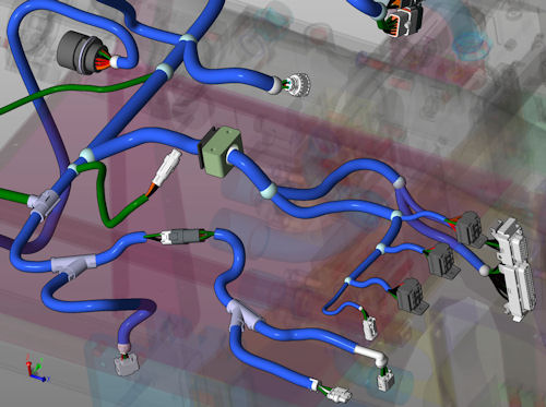
One of its key features is that Harness proD connects 3D data from MCAD and electrical design. This means you import your CATIA, Inventor, NX, SolidWorks, or Solid Edge model then develop your wiring and wire harness in a 3D model. As an aside, I should mention that you can use Harness proD as 2D wiring design tool without 3D data if you want.
Designing with Harness proD offers a lot of automation. It automatically identifies routing paths, routes wires and cables on previously defined paths, matches sockets, and places buffers, stoppers, and so forth. It also has test functions such as checks on minimum bending radii, cross-sections (also AWG), wire collisions, and on bundle diameters and length restrictions. It generates delivery dates, material calculations, weight calculations, and wiring and parts lists. Cable bundles are colored-coded, and you can open them and trace a wire without fuss.
When you’re done, you export the wired 3D model back to your MCAD solution for simulation. So, you can now find and fix design problems caused by wiring before physical prototyping. Since Harness proD incorporates its handiwork into your 3D model and builds parts lists, you also get your wiring data into your PDM/PLM system as well as your production systems. All this should compress development times and improve quality.
Today’s on-demand webcast is just over 30 minutes, and almost all of it is demonstration. I found the manner by which Harness proD goes about its business logical, concise, and thorough. And let me say this: There’s so much more going on here than I’ve gotten to. If you have anything at all to do with wire design, click the link over there and check out Harness proD.
Thanks, Pal. – Lockwood
Anthony J. Lockwood
Editor at Large, Desktop Engineering
Subscribe to our FREE magazine, FREE email newsletters or both!
About the Author
Anthony J. Lockwood is Digital Engineering’s founding editor. He is now retired. Contact him via [email protected].
Follow DE

