Wireless Design’s Diamond in the Rough
Two researchers at ORNL have developed a set of tools to design wireless networks.


Latest News
July 31, 2007
By Tom Kevan
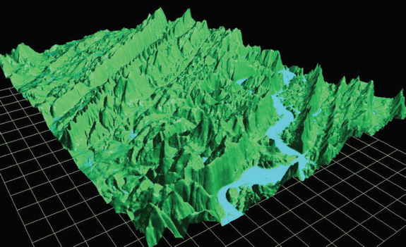 Fig 1: Digital elevation maps can be converted and used to develop site-specific coverage predictions using RCSIM. |
Leveraging data gleaned from extensive research and numerous deployments, commercial software for wireless network design offers well-developed interfaces and automated processes. These features deliver advantages in terms of ease of use and speedy results (see “Taming Wireless” in June 2007 DE), but commercial packages also have limitations.
To come up with a more flexible and accurate set of tools, Teja Kuruganti and James Nutaro, members of the Oak Ridge National Laboratory (ORNL) research staff, have developed Radio Channel Simulator (RCSIM). The program simulates the propagation of radio waves through a space in three dimensions (see Figure 1, above) and is tailored for the design of packet-based wireless networks.
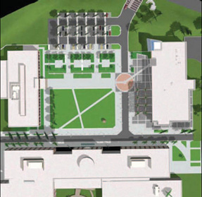 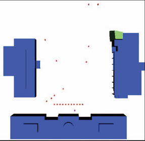 Fig 2: One of the first steps performed by RCSIM is to take a detailed 3D model of the environment (left) and convert it to a simplified X3D model (right). |
Building Your Model
With RCSIM, your first step is to draw a 3D model of the environment using an Extensible 3D (X3D)-compatible modeling tool (e.g., the open-source X3D-Edit software) and to save the file in a standard X3D format (see Figure 2, above). While any of the open-source X3D tools are suitable, bear in mind that there are restrictions on the kinds of X3D constructs that you can put into these models.
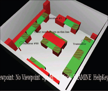 Fig 3: X3D models used by RCSIM include color-coded information on materials making up structures in the environment. |
Once you create a database containing the material properties of the physical structures making up the environment (e.g., wood, glass, metal, and concrete) you must color code the structures in the model so that the colors match up with the materials in the database (see Figure 3, at left). This portion of RCSIM’s conversion tool is still primitive.
“All the prepackaged data sets that you can get with many of the commercial tools are not available for our model at present,” says Nutaro. “You have to manually take a CAD drawing or something else, convert it into an appropriate X3D model, and feed it into our software. You also have to catalog all the material in the space, look up their electromagnetic properties, put the data into a table that our software can use, and develop a 3D model of the environment. It’s labor-intensive to get your raw data into our simulation system. ”
These initial steps are time-consuming and demand a level of expertise not usually possessed by the novice. Compared with the rich interfaces and automated processes of certain commercial packages, this aspect of RCSIM needs work.
The flip side of this issue is that many commercial packages with developed interfaces aren’t as able to deal with unique or unusual conditions. If they’re not covered by a propagation model in the software’s library, you lose most of the benefits of the automated processes. In contrast, these applications play to RCSIM’s strengths — fast, accurate, and streamlined simulation and analysis processes (see Figure 4, above).
Preparing for the Simulation
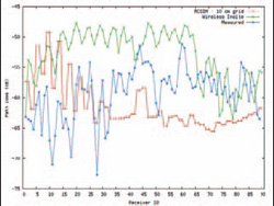 Fig 4: RCSIM simulations accurately predict radio wave propagation.The level of accuracy is shown in a comparison of measured and simulated signal-strength values from a study performed at Oak Ridge National Laboratory. |
The X3D model and material property information then go into the software’s grid-construction utility, which approximates the environment by dividing the 3D space into small grids, or cubes. Each of these cubes represents a piece of the total volume of the space. The result resembles a 3D model made of Lego blocks.
The software derives and attaches an electrical impedance characteristic and an attenuation coefficient to each of the cubes based on the material the cube represents, and the information resides in the database. Combined, the information gives you the approximate propagation geometry.
The Simulation
The output of the grid-construction utility goes next into the simulation program. You put a transmitter somewhere in the 3D space. The software predicts how a radio signal from the transmitter will move through the space by propagating the signal from cube to cube. At each cube, the software performs a handful of calculations to estimate wave reflection, signal attenuation, and the scattering process, which is the basic propagation mechanism. These calculations are performed only at cubes traversed by the radio signal, reducing the amount of computation required and speeding the simulation process.
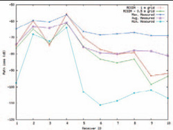 Fig 5:The results of an RCSIM validation study conducted at the Oak Ridge National Laboratory show that the average received signal strength corresponds well with the predictions made using RCSIM. |
The number of calculations performed during the simulation is further reduced by executing algorithms for strong signals only. “If the reflected or transmitted signal is so weak that you wouldn’t expect it to be picked up by the radio receiver, we throw it out and won’t continue to propagate it,” says Nutaro. “Typically, other grid-based methods will continue to propagate weak signals, but we track just the usable pieces of the signal as it moves through space.”
Ray Tracing vs. RCSIM
When it comes to getting the most accurate propagation results, the simulation approaches used by ray tracing and RCSIM deliver the best data. These deterministic methods are based on some approximation of the actual physical propagation process, as opposed to methods using stochastic models, which have nothing to do with the actual physics of the propagation problem.
In a head-to-head contest between ray tracing and RCSIM, RCSIM comes out on top not because it provides more accurate results but because it is more efficient.
With ray tracing, you simulate the propagation of radio waves by placing transmitters at various locations in the 3D space and then “shooting rays,” which represent possible signal paths through space. Basically, you shoot a ray and follow it until it intersects with a structure, compute how it reflects or transmits, and then follow the ray to the next structure and the next, until it reaches the receiver. In the end, you must shoot many rays to characterize all the possible paths the signal could follow. While accurate, this is time consuming and computationally intensive, and for large projects, it can require high-end workstations with serious processing and memory resources.
With RCSIM, most projects — large or small — can be performed with standard desktop computers. Using the approach of ORNL’s software, you get a more complete characterization of what’s going on in one shot of your calculation. Rather than track individual paths through space, the software uses scattering equations to construct all the possible paths simultaneously. The software also simplifies the simulation process by focusing on only strong, viable signals. These factors allow RCSIM to generate the final propagation result quickly and accurately (see Figure 5, above right), and it is less computationally intensive than design tools based on the ray tracing method.
“We did one propagation experiment that had 256,000 grid points,” says Nutaro. “For the ray-tracing model, this would translate to 256,000 potential receiver locations. With our method, we could do that in 5 minutes on a mid-range desktop computer. If you were to try to generate the same coverage map with a ray-tracing model, the projected completion time would be about 240 hours.”
Options
Currently, RCSIM runs on Linux systems, but the developers are trying to provide a Windows version. Although the software is not a commercial product, it is available for licensing, and you can obtain an evaluation copy under a beta test agreement by contacting Teja Kuruganti at 865-241-2874 or James Nutaro, at 865-241-1587. This is no empty promise. The gentlemen from ORNL have allowed other RF providers to use their tool set.
Tom Kevan is a New Hampshire-based freelance writer specializing in technology. Send your comments about this article to DE-Editorsmailto:[email protected].
Oak Ridge National Laboratory
Radio Channel Simulator RCSIM
Oak Ridge, TN
ornl.gov
Subscribe to our FREE magazine, FREE email newsletters or both!
Latest News
About the Author
DE’s editors contribute news and new product announcements to Digital Engineering.
Press releases may be sent to them via [email protected].


