
Optimized shape with a reduction in material, as calculated by solidThinking Inspire software.


July 15, 2015
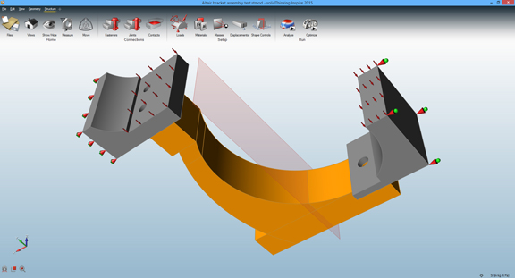 Setting up a multi-part assembly for optimization in solidThining Inspire 2015
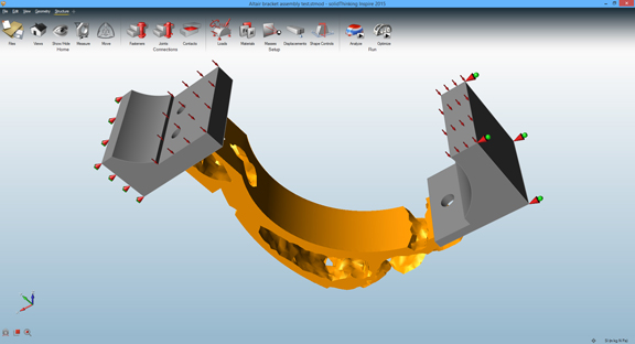 Optimized shape with a reduction in material, as calculated by Inspire software.
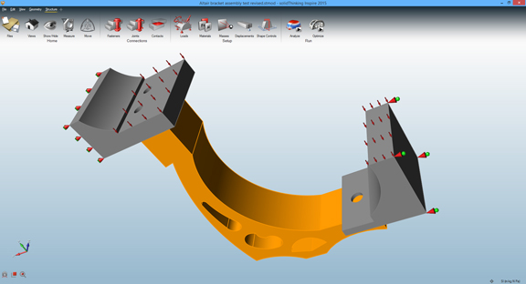 Part redesigned based on the optimized shape.
If you find simulation intimidating, you might find topology optimization doubly intimidating. The first discipline uses time-tested engineering principles, material science, and algorithms to calculate the effects of heat, stress, pressure, and wind on your product’s geometry. The second goes a step further. It uses modern computers’ impressive number-crunching capacity to analyze your product’s geometry, then proposes alternative shapes (or optimized topology) to counter the anticipated stresses. The learning curve for simulation software is steep enough; most optimization software comes with even a steeper learning curve. Many operates on top a high-end simulation program, so you need competency in simulation before you can perform optimization.
solidThinking Inspire is one of the few programs I know that makes topology optimization accessible to average engineers and designers. Some characteristics of Inspire’s user interface (UI) make it incredibly easy to understand the purpose of each command. Most software uses icons to communicate the function of a button or a command. But Inspire uses miniature 3D models to explain the functions of interface elements. For example, in the series of buttons available to simplify geometry, the hole-removal command is marked with a cube with a hole highlighted. Same goes for the blend-removal tool. These small touches make it instantly clear what you can expect to happen when you execute a command on your geometry.
Simplifying your geometry is often the first phase of optimization. Inspire has tools that lets you automatically identify holes and rounded edges to remove them; or plug gaps and crevices that need not be considered in the optimization process. While these details are important for the final production, they often don’t affect the stress calculation, so it’s prudent to remove them from your geometry beforehand.
In past versions, you can apply stresses and loads to individual parts for optimization. In Inspire 2015, you can analyze multiple parts joined or mated together. This is a significant change that lets you look at not only individual parts but assemblies with intricate relationships and joints. The software can automatically recognize features that call for joints and fasteners and insert them at the appropriate spots (such as holes that are perfect aligned).
Similar to the geometry-simplification commands, the analysis tools also offer clues with the use of miniature 3D models. Since mathematically optimized geometry seldom comes in easily manufacturable shapes, you can add some shape-controls to nudge the software toward generating shapes that are more suitable for stamping, machine, and so on. The software accomplishes this primarily in the way it forces symmetrical features onto the optimized geometry. (Symmetry is a regular feature of parts manufactured with classic production methods.)
Usually, the aim of optimization is to help you identify regions in your design where you have opportunities to remove excess materials, thereby reducing the cost of the product. So Inspire offers you in the final step a mass target. You may, for example, specify that your goal is to shave off materials by 35%. Once the software has solved the scenario, it offers an optimal shape within your target range, viewable with a slider bar that offers additional alternatives in decreasing or increasing mass.
Commonly, engineers tend to export the optimized shape as STL, IGES, or one of the common file formats into a CAD program so it can be used as guidance to redesign the original part. In doing so, you can come up with a design that uses less material, weighs significantly less, and costs less to produce. If needed, you can import the revised design into Inspire again for another round of assessment, evaluation, and optimization. The iterative process can go on until you arrive at a design that satisfies all the stress- and load-survival criteria and is within your budget.
For simulation experts, the pool of software choices for topology optimization is much larger, but for designers and engineers whose skills in simulation range from basic to limited, suitable optimization software is much harder to find. solidThinking Inspire should be on the short list for those users.
For more, watch the video report below:
Subscribe to our FREE magazine, FREE email newsletters or both!
About the Author
Kenneth Wong is Digital Engineering’s resident blogger and senior editor. Email him at [email protected] or share your thoughts on this article at digitaleng.news/facebook.
Follow DERelated Topics


