Latest News
November 4, 2010


In my view, the ideal hybrid CAD modeling experience is one in which you cease to make a distinction between direct editing and parametric editing. In other words, the two modeling methods are so well integrated that you don’t think about what mode you’re in; you simply use the command that suits you as you develop your geometry.
Solid Edge with Synchronous Technology 3 (SE with ST3), released last month, takes a significant leap in that direction, putting pressure on its rival who are on the same hybrid quest. This release lets you work on models containing both types of geometry: those created parametrically (what SE calls “Ordered features”) and those created in direct editing (what SE calls “Synchronous features”).
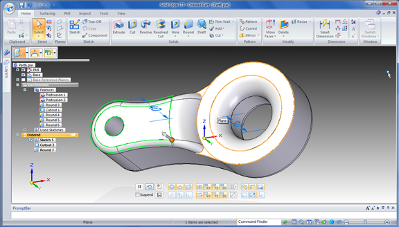
When you launch SE with ST3, you have the option to launch the new document either in Ordered mode (history-based mode) or Synchronous mode (direct-editing mode). By default, if you’re starting a part from scratch, SE with ST3 places you in Synchronous mode. But you can change the default setting. The command is a bit hard to find, but it’s located under the application menu > Solid Edge options > Helpers tab, as check marks.
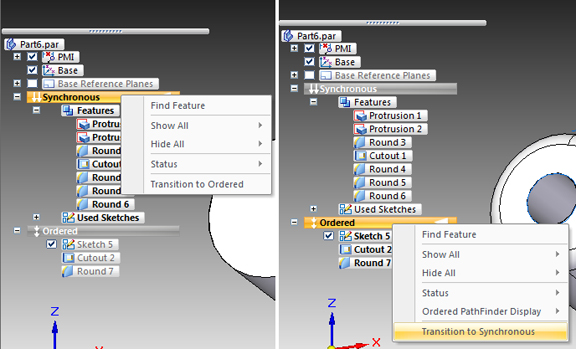
The beauty of this release is, if you feel the need to start pushing and pulling faces in the middle of an Ordered modeling session, you can simply select the stack of features you’d like to manipulate by direct editing, right-click, then select Transfer to Synchronous command. By doing so, you instantly place the selected group of geometry into the Synchronous category under the Path Finder pane (by default the pane sits on the left, where you would normally find a history tree or feature tree in a parametric CAD system).
Even if you have used classic parametric methods to build your geometry, once you transfer it to Synchronous, it becomes a collection of faces, so you can now use push-pull editing to further shape your geometry. This is not a one-way street. You can go the opposite direction too.
Suppose you’ve been working on a part in Synchronous mode, but need to add a new hole or boss that’s best created in history-based method. You can right-click and select Transition to Ordered. This gives you the ability to start adding new geometry or editing the existing shape using classic parametric modeling methods.
In essence, you can have a Path Finder pane with two stacks of features—Ordered and Synchronous—in the same modeling session. Depending on how you want to edit or shape your geometry, you can either work in Ordered or Synchronous mode—without having to launch a new program window, without having to convert the entire part to one or the other.
Another major enhancement in this release is its Create Part in Place function, which allows you to create and edit a part right within the context of an assembly. In general, CAD programs limit your ability to edit and create geometry in assembly mode. Let’s face it, almost all of them were developed to model parts, not assembly. The assembly mode is best described as the layout mode in 3D space, where you assemble the individual parts you’ve created into a fitted structure.
This presents a headache when you have the unenviable task of creating a component that must fit within a tight corner in an assembly. Traditionally, you take measurements of the space envelope, go into the Part modeling mode, create the part, place it in the assembly, find out where you have clashes, then go back to the Part mode to make adjustment ... and you repeat and rinse till all the mess gets cleaned up.
Not so in SE with ST3. When you invoke the Create Part in Place command, you’ll be prompted to specify your new part’s point of origin (its XYZ intersection). Then you’ll find yourself modeling a part, right inside the assembly structure. The other parts are in a lighter shade, deactivated so they won’t interfere with your new part. This gives you a much better option to build a part that’s custom-fitted in the narrow space within an assembly—without having to leave the assembly window.
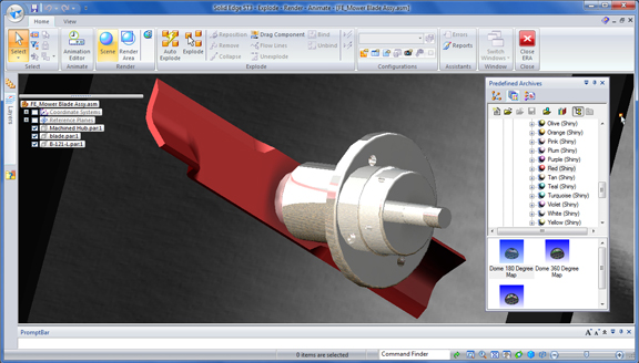
SE with ST3 also comes with a rendering and animation function. As you might expect, you can drag and drop materials, environment, and light studios to your modeling window to build your scene, then render the setup into a photo-realistic image. I’ll dig deeper into the new release in the next few months, so watch this space.
For more, watch the video demonstration below:
Subscribe to our FREE magazine, FREE email newsletters or both!
Latest News
About the Author
Kenneth Wong is Digital Engineering’s resident blogger and senior editor. Email him at [email protected] or share your thoughts on this article at digitaleng.news/facebook.
Follow DE


