Latest News
August 1, 2011
The premiere of Solid Edge with Synchronous Technology (SE with ST) in 2008 was a watershed moment. The ease with which the software allowed you to create and edit geometry with little or no concern for feature history challenged many conventions of mechanical modeling. It also opened the floodgate among parametric CAD vendors to pursue their own versions of history-free CAD.
The next milestone in SE with ST came in the third release, which, for the first time, allowed you to work in Ordered (history-based) mode and Synchronous (history-free) mode. The hybrid-modeling paradigm disproved the long-held belief that it’s not possible—nor is it a good idea—to mix direct edits and parametric edits.
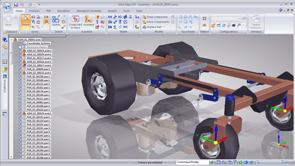
The added functions in SE with ST4 may not make you do a double-take, like the first and third releases did. But they add up to a robust collection of interface refinements that make you significantly more productive and efficient. Most of the enhancements are in assembly treatment, analysis, and visual display, indicating the software is maturing and settling on a stable UI.
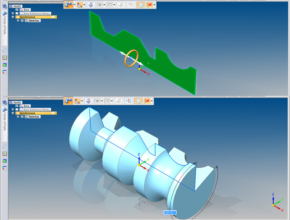
Steering a Revolution: In this release, the software introduces several new ways to use the steering wheel beyond the usual push-pull-rotate functions. If you align the steering wheel’s axis to the bottom of a 2D profile and touch the wheel (normally used to rotate faces), your active command changes to Revolve, instantly setting up an operation to revolve the profile into a 3D solid.
You may also use the same steering wheel in assembly mode, not just to drag your sub-assemblies along an axis but to position them along an arc. If you need to place a pair of identical sub-assemblies on opposite sides, facing each other (for example, two caps at both ends of a hollow cylinder), you select the part, activate the Move Copy command, reposition on the steering wheel to a midpoint between the desired distance (in this case, the mid-point of the shaft), and let the additional copy travel along a perfect arc, ending up on the opposite side in a position that mirrors the first.
Placing holes on cylindrical parts also gets easier in SE with ST4. The software gives you the option to slide holes along cylindrical surfaces in a tangent, so you don’t need to do extra work to align the hole with the center axis of the cylinder. Another minor improvement that goes along way: SE with ST has always prompted you with key-point indicators when you’re moving and positioning parts, but in this release, the indicators are a little easier to spot, thanks to the white border around the black symbols.
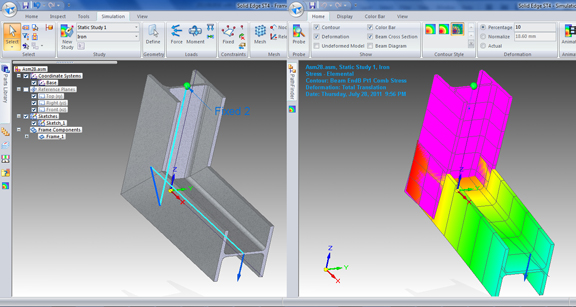
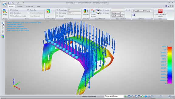
Straight Talk, Plane Talk: In SE’s Simulation environment (requires simulation license), you can now use two new mesh types. For sheet metal parts, or parts consisting primarily of plates, you can represent the parts using mid-surfaces—2D planes that correspond to the 3D part’s geometry. For structural frames, you can use 1D straight lines, called Beam Elements, to represent the crisscrossing frames. So why bother? By simplifying the geometry under consideration as mid-surfaces and straight lines, you may save CPU workload in meshing and solving.
Reflecting on Graphics: SE with ST4’s modeling window gives you the option to work in a graphically richer environment, with ground plane reflections and shadows. It also let you work in a Rendering mode, which provides you with a more realistic look to represent your design’s materials and colors. To get ray-traced rendering, however, you’ll need to leave the modeling window and move into the ERA mode (Explode, Render, Animate).
Facing Relations: A new tab called Face Relate in the main ribbon bar gives you a set of tools to build—and maintain—different types of relationships among faces. In theory, it seems straightforward enough. You click a face, click a relationship type (say, parallel), then click another face you want aligned to the first. Suddenly, you have two misaligned faces realigning themselves as parallel faces. In practice, however, I find that the results are often difficult to predict, especially when it involves more than two faces. The order in which I pick the faces seems to produce different results. At times, I also get stumped by the series of choices I need to make before the command executes (for example, whether I want the resulting face modifications to be extended or trimmed, whether I should prioritize the selected set of faces or the model, and so on). I’m hoping, in a future release, the same function can be implemented with a simpler workflow. (I’d like to hear what you think of this feature. If you have used it, please share your thoughts as comments.)
More reports and blog posts on SE with ST4 will appear as I dive deeper into the software. A print review of SE with ST4 is scheduled to appear in September issue of DE.
For a demonstration of the features discussed here, watch the video clip below.
Subscribe to our FREE magazine, FREE email newsletters or both!
Latest News
About the Author
Kenneth Wong is Digital Engineering’s resident blogger and senior editor. Email him at [email protected] or share your thoughts on this article at digitaleng.news/facebook.
Follow DE


